Featured post

Top 5 books to refer for a VHDL beginner

VHDL (VHSIC-HDL, Very High-Speed Integrated Circuit Hardware Description Language) is a hardware description language used in electronic des...

Showing posts with label UVM Methodology. Show all posts

Tuesday, 4 May 2021

UVM Interview Questions - 6

Q36: What is the Difference between UVM_ALL_ON and UVM_DEFAULT?

UVM_ALL_ON and UVM_DEFAULT are identical. As per the UVM reference manual:

UVM_ALL_ON: Set all operations on (default).
UVM_DEFAULT: Use the default flag settings.

It is recommended to use UVM_DEFAULT instead of UVM_ALL_ON even though they both essentially do the same thing today. At some point in time, the class library may add another "bit-flag" which may not necessarily be the DEFAULT.
If you use UVM_ALL_ON, that would imply that whatever flag it is would be "ON".


Q37: What drain time in UVM?

The drain time means the access time that you use before ending the simulation. Suppose if we are done with input traffic to the DUT didn't mean that nothing else would happen from that point as the DUT may have required some additional time to complete any transactions that were still being processed. Setting a drain time adds an extra delay from the time that all objections were dropped to the stop of the simulation, making sure that there were no outstanding transactions inside DUT at that point.

You can set the drain time in the base test at the end_of_elobration phase as shown below:

class test_base extends uvm_test;
  // ...
  
  function void end_of_elaboration_phase(uvm_phase phase);
    uvm_phase main_phase = phase.find_by_name("main", 0);
    main_phase.phase_done.set_drain_time(this, 10);
  endfunction
  
  // ...
endclass

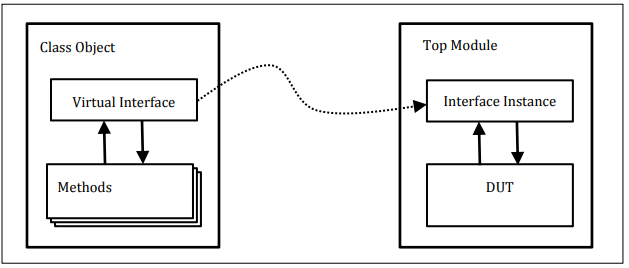
Q38: What is Virtual interface and how Virtual interface is used?

"Virtual interfaces are class data member handles that point to an interface instance. This allows a dynamic class object to communicate with a Design Under Test (DUT) module instance without using hierarchical references to directly access the DUT module ports or internal signals."


Below shown sample code is the easier way to use the virtual interface handles in the UVM environment. 
module top;
  …
  dut_if dif;
  …
  initial begin

    uvm_config_db#(virtual dut_if)::set(null, "*", "vif", dif);

    run_test();

  end
endmodule

class tb_driver extends uvm_driver #(trans1);
  …
  virtual dut_if vif;
  …
  function void build_phase(uvm_phase phase);
    super.build_phase(phase);

    // Get the virtual interface handle that was stored in the
    // uvm_config_db and assign it to the local vif field.
    if (!uvm_config_db#(virtual dut_if)::get(this, "", "vif", vif))
      `uvm_fatal("NOVIF", {"virtual interface must be set for: ",

     get_full_name(), ".vif"});
   endfunction
  …
endclass 
As shown first the actual interface or physical interface handle, dif, is stored into the uvm_config_db at string location "vif" using the set() command just before the run_test() call in the top level module.

Then it shows the use of the get() function of the uvm_config_db to retrieve the virtual interface handle from the same "vif" location and assign it to the local vif virtual interface handle in the driver class (the same code will be used inside of the monitor class as well).

Q39: How to add a user-defined phase in UVM?

If needed a user can create user-defined phases in the UVM environment. However, this may impact the re-usability of the component. To define a custom phase user need to extend the appropriate base class for phase-type. Following are the available base classes.

    class my_phase extends uvm_task_phase;
    class my_phase extends uvm_topdown_phase;
    class my_phase extends uvm_bottomup_phase;

You can refer to the UVM PHASE IMPLEMENTATION EXAMPLE for complete user-defined phase understanding.

Q40: How interface is passed to components in UVM?

The passing of interface is done using the virtual interface to the component is done using set() and get() methods. consider the below example:
Consider we have defined 2 interfaces as

apb_if intf0(.pclk(clk));
apb_if intf1(.pckl(clk));

Setting the interface:
initial begin
   //put in the database the interface used by APB agent agent0
   uvm_config_db#(virtual apb_if)::set(null, "uvm_test_top.env.agent0*", "VIRTUAL_INTERFACE", intf0);

   //put in the database the interface used by APB agent agent1
   uvm_config_db#(virtual apb_if)::set(null, "uvm_test_top.env.agent1*", "VIRTUAL_INTERFACE", intf1);
end


Getting the interface:
class cfs_apb_agent extends uvm_component;
   
   //pointer to the interface
   virtual cfs_apb_if vif;
   
   virtual function void build_phase(uvm_phase phase);
      super.build_phase(phase);
     
      if(uvm_config_db::#(virtual apb_if)::get(this, "", "VIRTUAL_INTERFACE", vif) == 0) begin
         `uvm_fatal("ISSUE", "Could not get from the database the virtual interface for the APB agent")
      end
   endfunction

endclass


<< PREVIOUS    NEXT >>

Saturday, 22 October 2016

Build smart tests using uvm_report_catcher

Today we will look into a very useful concept of UVM specially when we are doing any erroneous testing. Its all about modifying the severity, id, action, verbosity or the report string itself before the report is finally issued by the report server. 

Normally in our test environment shout for error when any erroneous scenario like CRC error condition or generation of any error interrupt occurs. And we also write erroneous tests to test these scenarios where we end-up with error messages and tests fails. 

The uvm_report_catcher is used to catch messages issued by the uvm report server. Upon catching a report, the catch method can modify the severity, id, action, verbosity or the report string itself before the report is finally issued by the report server.  The report can be immediately issued from within the catcher class by calling the issue method.

The catcher maintains a count of all reports with FATAL, ERROR or WARNING severity and a count of all reports with FATAL, ERROR or WARNING severity whose severity was lowered.  These statistics are reported in the summary of the uvm_report_server.

Example: 

Report catcher class:
class error_report_catcher extends uvm_report_catcher;
  //new constructor
  virtual function action_e catch();
    if(get_severity() == UVM_ERROR && get_id() == "MON_CHK_NOT_VALID") begin
      set_severity(UVM_INFO);
      return CAUGHT;
    end
    else begin
      return THROW;
    end
  endfunction
endclass : error_report_catcher_c


Use of error catcher in testcase: 
class erroneous_test extends base_test_class;

  // report catcher to suppress errors
  error_report_catcher error_catcher ;
  /// \fn new_constructor
   
  /// \fn build_phase
virtual function void build_phase(uvm_phase phase);
    super.build_phase(phase);
      error_catcher = new();
      uvm_report_cb::add(null,error_catcher) ;
      uvm_config_db#(int)::set(this,“uvc.tx_agent","is_active",UVM_ACTIVE);
         
      // User configurations
      env_cfg.print();
      uvm_config_db#(env_config_c)::set(this, "*" , “env_cfg", env_cfg);
      // Calling the error sequence
      uvm_config_db#(uvm_object_wrapper)::set(this, “uvc.tx_agent.tx_sequencer.main_phase","default_sequence",valid_invalid_seq_c::type_id::get());
  endfunction : build_phase

endclass : erroneous_test

Tuesday, 10 November 2015

UVM Interview Questions - 5

Q31: What is virtual sequencer and virtual sequence in UVM?

A virtual sequencer is a sequencer that is not connected to a driver itself, but contains handles for sequencers in the testbench hierarchy. It is an optional component for running of virtual sequences - optional because they need no driver hookup, instead calling other sequences which run on real sequencers.

A sequence which controls stimulus generation across more than one sequencer, coordinate the stimulus across different interfaces and the interactions between them. Usually the top level of the sequence hierarchy i.e. 'master sequence' or 'coordinator sequence'. Virtual sequences do not need their own sequencer, as they do not link directly to drivers. When they have one it is called a virtual sequencer.

Here is a good article which explains how to use virtual sequence and virtual sequencer.

http://www.learnuvmverification.com/index.php/2016/02/23/how-virtual-sequence-works-part-1/


Q32: How set_config_* works?

The uvm_config_db class provides a convenience interface on top of the uvm_resource_db to simplify the basic interface that is used for configuring uvm_component instances.

Configuration is a mechanism in UVM that higher level components in a hierarchy can configure the lower level components variables. Using set_config_* methods, user can configure integer, string and objects of lower level components. Without this mechanism, user should access the lower level component using hierarchy paths, which restricts re-usability.

This mechanism can be used only with components. Sequences and transactions cannot be configured using this mechanism. When set_config_* method is called, the data is stored w.r.t strings in a table. There is also a global configuration table.

Higher level component can set the configuration data in level component table. It is the responsibility of the lower level component to get the data from the component table and update the appropriate table.

following are the method to configure integer, string and object of uvm_object based class respectively.

function void set_config_int (string inst_name, string field_name, uvm_bitstream_t value)

function void set_config_string (string inst_name, string field_name, string value)

function void set_config_object (string inst_name, string field_name, uvm_object value, bit clone = 1)

Q33: What are the advantages of uvm RAL model ?

  • The RAL (register abstraction layer) provides accesses to DUT and also keeps a track of register content of DUT.
  • UVM RAL can be used to automate the creation of high level, object oriented abstraction model of registers and memory in DUT.
  • Register layer makes the register abstraction and access of its contents independent of the bus protocol which is used to transfer data in and out of registers inside the design.
  • Hierarchical model provided by RAL makes the reusability of test bench components very easy.
  • The changes in initial configuration of registers or specifications can be easily communicated in the entire environment. RAL layer supports both front door and backdoor access. The backdoor access does not use the bus interface rather it uses the HDL defined paths for direct communication with the device. Thus in zero simulation time the registers of device can be reconfigured using the backdoor access and verification can be started.
  • One more advantage of backdoor access is that it can be used for verify if the access through front door are happening correctly. To achieve this the front door, write is verified using backdoor read.

Q34: What are the different override types?

Two type of overriding is supported by UVM

1. Type overriding

Type overriding means that every time a component class type is created in the Testbench hierarchy, a substitute type i.e. derived class of the original component class, is created in its place. It applies to all the instances of that component type.

Syntax:
<original_type>::type_id::set_type_override(<substitute_type>::get_type(), replace);

where “replace” is a bit which is when set equals to 1, enables the overriding of an existing override else existing override is honoured.

2. Instance overriding

In Instance Overriding, as name indicates it substitutes ONLY a particular instance of the component OR a set of instances with the intended component. The instance to be substituted is specified using the UVM component hierarchy.

Syntax:
<original_type>::type_id::set_inst_override(<substitute_type>::get_type(), <path_string>);

Where “path_string” is the hierarchical path of the component instance to be replaced.

Q35: Explain end of simulation in UVM?
Different approaches to finish the UVM Test using the objection mechanism are
1. Raising & dropping objections
raise_objection() and drop_objection() are the methods to be used to do that.
2. phase_ready_to_end
phase_ready_to_end method is executed automatically by UVM once ‘all dropped’ condition is achieved during Run Phase.
3. set_drain_time
Another approach supported by UVM is setting the drain time for the simulation environment. Drain time concept is related to the extra time allocated to the UVM environment to process the left over activities e.g. last packet analysis & comparison etc after all the stimulus is applied & processed.
<< PREVIOUS        NEXT >>

Friday, 11 September 2015

UVM Interview Questions - 4

Q26: What is p_sequencer ? OR Difference between m_sequencer and p_sequencer?

m_sequencer is the default handle for uvm_vitual_sequencer and p_sequencer is the hook up for child sequencer.

m_sequencer is the generic uvm_sequencer pointer. It will always exist for the uvm_sequence and is initialized when the sequence is started.

p_sequencer is a typed-specific sequencer pointer, created by registering the sequence to the sequencer using macros (`uvm_declare_p_sequencer) . Being type specific, you will be able to access anything added to the sequencer (i.e. pointers to other sequencers, etc.). p_sequencer will not exist if we have not registered the sequence with the `uvm_declare_p_sequencer macros.

The drawback of p_sequencer is that once the p_sequencer is defined, one cannot run the sequence on any other sequencer type.


Q27: What is the difference between Active mode and Passive mode with respect to agent?

An agent is a collection of a sequencer, a driver and a monitor.

In active mode, the sequencer and the driver are constructed and stimulus is generated by sequences sending sequence items to the driver through the sequencer. At the same time the monitor assembles pin level activity into analysis transactions.

In passive mode, only the monitor is constructed and it performs the same function as in an active agent. Therefore, your passive agent has no need for a sequencer. You can set up the monitor using a configuration object.

Q28: What is the difference between copy and clone?

The built-in copy() method executes the __m_uvm_field_automation() method with the required copy code as defined by the field macros (if used) and then calls the built-in do_copy() virtual function. The built-in do_copy() virtual function, as defined in the uvm_object base class, is also an empty method, so if field macros are used to define the fields of the transaction, the built-in copy() method will be populated with the proper code to copy the transaction fields from the field macro definitions and then it will execute the empty do_copy() method, which will perform no additional activity.

The copy() method can be used as needed in the UVM testbench. One common place where the copy() method is used is to copy the sampled transaction and pass it into a sb_calc_exp() (scoreboard calculate expected) external function that is frequently used by the scoreboard predictor.

The clone() method calls the create() method (constructs an object of the same type) and then calls the copy() method. It is a one-step command to create and copy an existing object to a new object handle.

Q29: What is UVM factory? 

UCM Factory is used to manufacture (create) UVM objects and components. Apart from creating the UVM objects and components the factory concept essentially means that you can modify or substitute the nature of the components created by the factory without making changes to the testbench. 

For example, if you have written two driver classes, and the environment uses only one of them. By registering both the drivers with the factory, you can ask the factory to substitute the existing driver in environment with the other type. The code needed to achieve this is minimal, and can be written in the test.

Q30: What are the types of sequencer? Explain each?

There are two types of sequencers :

uvm_sequencer #(REQ, RSP) :
When the driver initiates new requests for sequences, the sequencer selects a sequence from a list of available sequences to produce and deliver the next item to execute. In order to do this, this type of sequencer is usually connected to a driver uvm_driver #(REQ, RSP).

uvm_push_sequencer #(REQ, RSP) :
The sequencer pushes new sequence items to the driver, but the driver has the ability to block the item flow when its not ready to accept any new transactions. This type of sequencer is connected to a driver of type uvm_push_driver #(REQ, RSP).


Thursday, 10 September 2015

UVM Interview Questions - 3

Q21: What is analysis port?

Analysis port (class uvm_tlm_analysis_port) — a specific type of transaction-level port that can be connected to zero, one, or many analysis exports and through which a component may call the method write implemented in another component, specifically a subscriber.

port, export, and imp classes used for transaction analysis.

uvm_analysis_port
Broadcasts a value to all subscribers implementing a uvm_analysis_imp.
uvm_analysis_imp
Receives all transactions broadcasted by a uvm_analysis_port.
uvm_analysis_export
Exports a lower-level uvm_analysis_imp to its parent.


Q22: What is TLM FIFO?

In simpler words TLM FIFO is a FIFO between two UVM components, preferably between Monitor and Scoreboard. Monitor keep on sending the DATA, which will be stored in TLM FIFO, and Scoreboard can get data from TLM FIFO whenever needed.

// Create a FIFO with depth 4
      tlm_fifo = new ("uvm_tlm_fifo", this, 4);


Q23: How sequence starts?
start_item starts the sequence

virtual task start_item ( uvm_sequence_item item,  
                                          int  set_priority =  -1,
                                        uvm_sequencer_base  sequencer =  null )

start_item and finish_item together will initiate operation of a sequence item.  If the item has not already been initialized using create_item, then it will be initialized here to use the default sequencer specified by m_sequencer. 

Q24: What is the difference between UVM RAL model backdoor write/read and front door write/read ?

Fontdoor access means using the standard access mechanism external to the DUT to read or write to a register. This usually involves sequences of time-consuming transactions on a bus interface. 

Backdoor access means accessing a register directly via hierarchical reference or outside the language via the PLI. A backdoor reference usually in 0 simulation time.

Q25: What is objection?

The objection mechanism in UVM is to allow hierarchical status communication among components which is helpful in deciding the end of test.

There is a built-in objection for each in-built phase, which provides a way for components and objects to synchronize their testing activity and indicate when it is safe to end the phase and, ultimately, the test end.

The component or sequence will raise a phase objection at the beginning of an activity that must be completed before the phase stops, so the objection will be dropped at the end of that activity. Once all of the raised objections are dropped, the phase terminates.

Raising an objection: phase.raise_objection(this);
Dropping an objection: phase.drop_objection(this);

<< PREVIOUS       NEXT >>

Wednesday, 9 September 2015

UVM Interview Questions - 1

Q11: Difference between module & class based TB?

Ans: A module is a static object present always during of the simulation.
A Class is a dynamic object because they can come and go during the life time of simulation.

Q12: What is uvm_config_db ? What is difference between uvm_config_db & uvm_resource_db?

Ans: uvm_config_db is a parameterized class used for configuration of different type of parameter into the uvm database, So that it can be used by any component in the lower level of hierarchy.

uvm_config_db is a convenience layer built on top of uvm_resource_db, but that convenience is very important. In particular, uvm_resource_db uses a "last write wins" approach. The uvm_config_db, on the other hand, looks at where things are in the hierarchy up through end_of_elaboration, so "parent wins." Once you start start_of_simulation, the config_db becomes "last write wins."

All of the functions in uvm_config_db#(T) are static, so they must be called using the :: operator
It is extended from the uvm_resource_db#(T), so it is child class of uvm_resource_db#(T)

Q13: What is the advantage and difference of  `uvm_component_utils() and `uvm_object_utils()?

Ans: The utils macros define the infrastructure needed to enable the object/component for correct factory operation. 

The reason there are two macros is because the factory design pattern fixes the number of arguments that a constructor can have. Classes derived from uvm_object have constructors with one argument, a string name. Classes derived from uvm_component have two arguments, a name and a uvm_component parent.  

The two `uvm_*utils macros inserts code that gives you a factory create() method that delegates calls to the constructors of uvm_object or uvm_component. You need to use the respective macro so that the correct constructor arguments get passed through. This means that you cannot add extra constructor arguments when you extend these classes in order to be able to use the UVM factory.

Q14: Difference between `uvm_do and `uvm_rand_send ?

Ans: `uvm_do perform the below steps:
  1. create
  2. start_item
  3. randomize
  4. finish_item
  5. get_response (optional)

while `uvm_rand_send perform all the above steps except create. User needs to create sequence / sequence_item.

Q15: Difference between uvm_transaction and uvm_seq_item?

Ans: class uvm_sequence_item extends uvm_transaction

uvm_sequence_item extended from uvm_transaction only, uvm_sequence_item class has more functionality to support sequence & sequencer features. uvm_sequence_item provides the hooks for sequencer and sequence , So you can generate transaction by using sequence and sequencer , and uvm_transaction provide only basic methods like do_print and do_record etc .


UVM Interview Questions - 2

Q16: Is uvm is independent of systemverilog ?

Ans: UVM is a methodology based on SystemVerilog language and is not a language on its own.  It is a standardized methodology that defines several best practices in verification to enable  efficiency in terms of reuse and is also currently part of IEEE 1800.2  working group.

Q17: What are the benefits of using UVM?

Ans: Some of the benefits of using UVM are :

  • Modularity and Reusability – The methodology is designed as modular components (Driver, Sequencer, Agents , env etc) which enables reusing components across unit level to multi-unit or chip level verification as well as across projects.
  • Separating Tests from Testbenches – Tests in terms of stimulus/sequencers are kept separate from the actual testbench hierarchy and hence there can be reuse of stimulus across different units or across projects
  • Simulator independent – The base class library and the methodology is supported by all simulators and hence there is no dependence on any specific simulator
  • Better control on Stimulus generation – Sequence methodology gives good control on stimulus generation. There are several ways in which sequences can be developed which includes randomization, layered sequences, virtual sequences etc which provides a good control and rich stimulus generation capability.
  • Easy configuration – Config mechanisms simplify configuration of objects with deep hierarchy. The configuration mechanism helps in easily configuring different testbench components based on which verification environment uses it and without worrying about how deep any component is in testbench hierarchy
  • Factory mechanism – Factory mechanisms simplifies modification of components easily. Creating each components using factory enables them to be overridden in different tests or environments without changing underlying code base.


Q18: Can we have user defined phase in UVM?

Ans: In addition to the predefined phases available in uvm , the user has the option to add his own phase to a component. This is typically done by extending the uvm_phase class the constructor needs to call super.new which has three arguments
  • Name of the phase task or function
  • Top down or bottom up phase
  • Task or function


The call_task  or call_func and get_type_name need to be implemented to complete the addition of new phase.
Below is a simple example 

Example
class custom_phase extends uvm_phase;
   function new();
      super.new(“custom”,1,1);
   endfunction

   task call_task  ( uvm_component parent);
     my_comp_type comp;
     if ( $cast(comp,parent) )
             comp.custom_phase();
   endtask

   virtual function string get_type_name();
      return “custom”;
   endfunction
endclass


Q19: What is uvm RAL model ? why it is required ?

Ans: In a verification context, a register model (or register abstraction layer) is a set of classes that model the memory mapped behavior of registers and memories in the DUT in order to facilitate stimulus generation and functional checking (and optionally some aspects of functional coverage). The UVM provides a set of base classes that can be extended to implement comprehensive register modeling capabilities.

Q20: What is the difference between new() and create?

Ans: We all know about new() method that is use to allocate memory to an object instance. In UVM (and OVM), the create() method causes an object instance to be created from the factory. This allows you to use factory overrides to replace the desired object with an object of a different type without having to recode.

<< PREVIOUS      NEXT >>

UVM Interview Questions

Q1: What is UVM? What is the advantage of UVM?

Ans: UVM (Universal Verification Methodology) is a standardized methodology for verifying the both complex & simple digital design in simple way.

UVM Features:
  • First methodology & second collection of class libraries for Automation
  • Reusability through testbench
  • Plug & Play of verification IPs
  • Generic Testbench Development
  • Vendor & Simulator Independent
  • Smart Testbench i.e. generate legal stimulus as from pre-planned coverage plan
  • Support CDV –Coverage Driven Verification
  • Support CRV –Constraint Random Verification
  • UVM standardized under the Accellera System Initiative
  • Register modeling

Q2: UVM derived from which language?

Ans: Here is the detailed connection between SV, UVM, OVM and other methodologies. 


Q3. What is the difference between uvm_component and uvm_object?
                       OR
We already have uvm_object, why do we need uvm_component which is actually derived class of uvm_object?

Ans: 
uvm_component:
  • Quasi Static Entity (after build phase it is available throughout the simulation)
  • Always tied to a given hardware(DUT Interface) Or a TLM port
  • Having phasing mechanism for control the behavior of simulation
  • Configuration Component Topology

uvm_object:
  • Dynamic Entity (create when needed, transfer from one component to other & then dereference)
  • Not tied to a given hardware or any TLM port
  • Not phasing mechanism 

Q4: Why phasing is used? What are the different phases in uvm?

Ans: UVM Phases is used to control the behavior of simulation in a systematic way & execute in a sequential ordered to avoid race condition. This could also be done in system verilog but manually.
  1. List of UVM Phases:
  2. buid_phase
  3. connect_phase
  4. end_of_elaboration_phase
  5. start_of_simulation_phase       
  6. run _phase  (task)
    Sub Phases of Reset Phase:
    pre_reset_phase
    reset_phase
    post_reset_phase
    pre_configure_phase
    configure_phase
    post_configure_phase
    pre_main_phase
    main_phase
    post_main_phase
    pre_shutdown_phase
    shutdown_phase
    post_shutdown_phase
  7. extract_phase
  8. check_phase
  9. report_phase
Below figure makes it more clear


Q5: Which uvm phase is top - down , bottom – up & parallel?

Ans: Only build phase is a top-down & other phases are bottom-up except run phase which is parallel. The build phase works top-down since the testbench hierarchy may be configure so we need to build the branches before leafs

Q6: Why build phase is top – down & connect phase is bottom – up?

Ans: The connect phase is intended to be used for making TLM connections between components, which is why it occur after build phase. It work bottom-up so that its got the correct implementation all the way up the design hierarchy, if worked top-down this would be not possible

Q7: Which phase is function & which phase is task?

Ans: Only run phase is a task (time consuming phase) & other phases are functions (non-blocking)

Q8: Which phase takes more time and why?

Ans: As previously said the run phase is implemented as task and remaining all are function. run phase will get executed from start of simulation to till the end of simulation. run phase is time consuming, where the testcase is running.

Q9: How uvm phases initiate?

Ans: UVM phases initiate by calling run_test(“test1”) in top module. When run_test() method call, it first create the object of test top & then call all phases.

Q10: How test cases run from simulation command line?

Ans: In top module write run_test(); i.e. Don't give anything in argument.
Then in command line : +UVM_TESTNAME=testname

Monday, 24 November 2014

UVM - Driver

The driver is a block whose role is to interact with the DUT. The driver pulls transactions from the sequencer and sends them repetitively to the signal-level interface. This interaction will be observed and evaluated by another block, the monitor, and as a result, the driver’s functionality should only be limited to send the necessary data to the DUT.

In order to interact with our adder, the driver will execute the following operations: control the en_i signal, send the transactions pulled from the sequencer to the DUT inputs and wait for the adder to finish the operation.

So, we are going to follow these steps:

  1. Derive the driver class from the uvm_driver base class
  2. Connect the driver to the signal interface
  3. Get the item data from the sequencer, drive it to the interface and wait for the DUT execution
  4. Add UVM macros

In Code 5.1 you can find the base code pattern which is going to be used in our driver.

class simpleadder_driver extends uvm_driver#(simpleadder_transaction);
`uvm_component_utils(simpleadder_driver)   //Interface declaration
protected virtual simpleadder_if vif;   function new(string name, uvm_component parent);
super.new(name, parent);
endfunction: new   function void build_phase(uvm_phase phase);
super.build_phase(phase);
void'(uvm_resource_db#(virtual simpleadder_if)::read_by_name(.scope("ifs"), .name("simpleadder_if"), .val(vif)));
endfunction: build_phase   task run_phase(uvm_phase phase);
//Our code here
endtask: run_phase
endclass: simpleadder_driver
Code 5.1 – Driver component – simpleadder_driver.sv

The code might look complex already but what it’s represented it’s the usual code patterns from UVM. We are going to focus mainly on the run_phase() task which is where the behaviour of the driver will be stated. But before that, a simple explanation of the existing lines will be given:


  • Line 1 derives a class named simpleadder_driver from the UVM class uvm_driver. The #(simpleadder_transaction) is a SystemVerilog parameter and it represents the data type that it will be retrieved from the sequencer.


  • Line 2 refers to the UVM utilities macro explained on chapter 2.


  • Lines 7 to 9 are the class constructor.


  • Line 11 starts the build phase of the class, this phase is executed before the run phase.


  • Line 13 gets the interface from the factory database. This is the same interface we instantiated earlier in the top block.


  • Line 16 is the run phase, where the code of the driver will be executed.

Now that the driver class was explained, you might be wondering: “What exactly should I write in the run phase?”

Consulting the state machine from the chapter 1, we can see that the DUT waits for the signal en_i to be triggered before listening to the ina and inb inputs, so we need to emulate the states 0 and 1. Although we don’t intend to sample  the output of the DUT with the driver, we still need to respect it, which means, before we send another sequence, we need to wait for the DUT to output the result.

To sum up, in the run phase the following actions must be taken into account:


  1. Get a sequence item


  2. Control the en_i signal


  3. Drive the sequence item to the bus


  4. Wait a few cycles for a possible DUT response and tell the sequencer to send the next sequence item

The driver will end its operation the moment the sequencer stops sending transactions. This is done automatically by the UVM API, so the designer doesn’t need to to worry with this kind of details.

In order to write the driver, it’s easier to implement the code directly as a normal testbench and observe its behaviour through waveforms. As a result, in the next subchapter (chapter 5.1), the driver will first be implemented as a normal testbench and then we will reuse the code to implement the run phase (chapter 5.2).

Chapter 5.1 – Creating the driver as a normal testbench


For our normal testbench we will use regular Verilog code. We will need two things: generate the clock and idesginate an end for the simulation. A simulation of 30 clock cycles was defined for this testbench.

The code is represented in Code 5.2.

//Generates clock
initial begin
#20;
forever #20 clk = ! clk;
end   //Stops testbench after 30 clock cyles
always@(posedge clk)
begin
counter_finish = counter_finish + 1;   if(counter_finish == 30) $finish;
end
Code 5.2 – Clock generation for the normal testbench
The behaviour of the driver follows in Code 5.3.
//Driver
always@(posedge clk)
begin
//State 0: Drives the signal en_o
if(counter_drv==0)
begin
en_i = 1'b1;
state_drv = 1;
end   if(counter_drv==1)
begin
en_i = 1'b0;
end   case(state_drv)
//State 1: Transmits the two inputs ina and inb
1: begin
ina = tx_ina[1];
inb = tx_inb[1];   tx_ina = tx_ina << 1;
tx_inb = tx_inb << 1;   counter_drv = counter_drv + 1;
if(counter_drv==2) state_drv = 2;
end   //State 2: Waits for the DUT to respond
2: begin
ina = 1'b0;
inb = 1'b0;
counter_drv = counter_drv + 1;   //After the supposed response, the TB starts over
if(counter_drv==6)
begin
counter_drv = 0;
state_drv = 0;   //Restores the values of ina and inb
//to send again to the DUT
tx_ina <= 2'b11;
tx_inb = 2'b10;
end
end
endcase
end
Code 5.3 – Part of the driver

For this testbench, we are sending the values of tx_ina and  tx_inb to the DUT, they are defined in the beginning of the testbench (you can see the complete code attached to this guide).

We are sending the same value multiple times to see how the driver behaves by sending consecutive transactions.

After the execution of the Makefile, a file named simpleadder.dump will be created by VCS. To see the waveforms of the simulation, we just need to open it with DVE.

The waveform for the driver is represented on Figure 5.1.

ch6-tb_driver_waveform

It’s possible to see that the driver is working as expected: it drives the signal en_i on and off as well the DUT inputs ina and inb and it waits for a response of the DUT before sending the transaction again.

Chapter 5.2 – Implementing the UVM driver

After we have verified that our driver behaves as expected, we are ready to move the code into the run phase as seen in Code 5.4.

virtual task drive();
simpleadder_transaction sa_tx;
integer counter = 0, state = 0;
vif.sig_ina = 0'b0;
vif.sig_inb = 0'b0;
vif.sig_en_i = 1'b0;   forever begin
if(counter==0) begin
//Gets a transaction from the sequencer and
//stores it in the variable 'sa_tx'
seq_item_port.get_next_item(sa_tx);
end   @(posedge vif.sig_clock)
begin
if(counter==0) begin
vif.sig_en_i = 1'b1;
state = 1;
end   if(counter==1) begin
vif.sig_en_i = 1'b0;
end   case(state)
1: begin
vif.sig_ina = sa_tx.ina[1];
vif.sig_inb = sa_tx.inb[1];   sa_tx.ina = sa_tx.ina &lt;&lt; 1;
sa_tx.inb = sa_tx.inb &lt;&lt; 1;   counter = counter + 1;
if(counter==2) state = 2;
end   2: begin
vif.sig_ina = 1'b0;
vif.sig_inb = 1'b0;
counter = counter + 1;   if(counter==6) begin
counter = 0;
state = 0;   //Informs the sequencer that the
//current operation with
//the transaction was finished
seq_item_port.item_done();
end
end
endcase
end
end
endtask: drive
Code 5.4 - Task for the run_phase()

The ports of the DUT are acessed through the virtual interface with vif.<signal> as can be seen in lines 4 to 6.

Lines 12 and 50 use a special variable from UVM, the seq_item_port to communicate with the sequencer. The driver calls the method get_next_item() to get a new transaction and once the operation is finished with the current transaction, it calls the method item_done(). If the driver calls get_next_item() but the sequencer doesn’t have any transactions left to transmit, the current task returns.

This variable is actually a UVM port and it connects to the export from the sequencer named seq_item_export. The connection is made by an upper class, in our case, the agent. Ports and exports are going to be further explained in chapter 6.0.1.

This concludes our driver, the full code for the driver can be found in the filesimpleadder_driver.sv. In Figure 5.2, the state of the verification environment with the driver can be seen.

ch6-uvm_tb_simpleadder_driver

Figure 5.2 – State of the verification environment with the driver

Saturday, 25 October 2014

UVM - Sequences and sequencers

The first step in verifying a RTL design is defining what kind of data should be sent to the DUT. While the driver deals with signal activities at the bit level, it doesn’t make sense to keep this level of abstraction as we move away from the DUT, so the concept of transaction was created.

A transaction is a class object, usually extended from uvm_transaction or uvm_sequence_item classes, which includes the information needed to model the communication between two or more components.

Transactions are the smallest data transfers that can be executed in a verification model. They can include variables, constraints and even methods for operating on themselves. Due to their high abstraction level, they aren’t aware of the communication protocol between the components, so they can be reused and extended for different kind of tests if correctly programmed.

An example of a transaction could be an object that would model the communication bus of a master-slave topology. It could include two variables: the address of the device and the data to be transmitted to that device. The transaction would randomize these two variables and the verification environment would make sure that the variables would assume all possible and valid values to cover all combinations.

In order to drive a stimulus into the DUT, a driver component converts transactions into pin wiggles, while a monitor component performs the reverse operation, converting pin wiggles into transactions.

After a basic transaction has been specified, the verification environment will need to generate a collection of them and get them ready to be sent to the driver. This is a job for the sequence. Sequences are an ordered collection of transactions, they shape transactions to our needs and generate as many as we want. This means if we want to test just a specific set of addresses in a master-slave communication topology, we could restrict the randomization to that set of values instead of wasting simulation time in invalid values.

Sequences are extended from uvm_sequence and their main job is generating multiple transactions. After generating those transactions, there is another class that takes them to the driver: the sequencer. The code for the sequencer is usually very simple and in simple environments, the default class from UVM is enough to cover most of the cases.

A representation of this operation is shown in Figure 4.1.

ch5-uvm_tb_sequence

Figure 4.1 - Relation between a sequence, a sequencer and a driver

The sequence englobes a group of transactions and the sequencer takes a transaction from the sequence and takes it to the driver.

To test our DUT we are going to define a simple transaction, extended fromuvm_sequence_item. It will include the following variables:

rand bit[1:0] ina
rand bit[1:0] inb
bit[2:0] out

The variables ina and inb are going to be random values to be driven to the inputs of the DUT and the variable out is going to store the result. The code for the transaction is represented in Code 4.1.

class simpleadder_transaction extends uvm_sequence_item;
     rand bit[1:0] ina;
     rand bit[1:0] inb;
     bit[2:0] out;
 
     function new(string name = "");
          super.new(name);
     endfunction: new
 
     `uvm_object_utils_begin(simpleadder_transaction)
     `uvm_field_int(ina, UVM_ALL_ON)
     `uvm_field_int(inb, UVM_ALL_ON)
     `uvm_field_int(out, UVM_ALL_ON)
     `uvm_object_utils_end
endclass: simpleadder_transaction
Code 4.1 – Transaction for the simpleadder

An explanation of the code will follow:

  • Lines 2 and 3 declare the variables for both inputs. The rand keyword asks the compiler to generate and store random values in these variables.
  • Lines 6 to 8 include the typical class constructor.
  • Lines 10 to 14 include the typical UVM macros.

These few lines of code define the information that is going to be exchanged between the DUT and the testbench.

To demonstrate the reuse capabilities of UVM, let’s imagine a situation where we would want to test a similar adder with a third input, a port named inc.

Instead of rewriting a different transaction to include a variable for this port, it would be easier just to extend the previous class to support the new input.

It’s possible to see an example in Code 5.2.

class simpleadder_transaction_3inputs extends simpleadder_transaction;
     rand bit[1:0] inc;
 
     function new(string name = "");
          super.new(name);
     endfunction: new
 
     `uvm_object_utils_begin(simpleadder_transaction_3inputs)
     `uvm_field_int(inc, UVM_ALL_ON)
     `uvm_object_utils_end
endclass: simpleadder_transaction_3inputs
Code 5.2 – Extension of the previous transaction

As a result of the class simpleadder_transaction_3inputs being an extension of  simpleadder_transaction, we didn’t need to declare again the other variables. While in small examples, like this one, this might not look like something useful, for bigger verification environments, it might save a lot of work.

Sequence

Now that we have a transaction, the next step is to create a sequence.

The code for the sequencer can be found in Code 5.3

class simpleadder_sequence extends uvm_sequence#(simpleadder_transaction);
     `uvm_object_utils(simpleadder_sequence)
 
     function new(string name = "");
          super.new(name);
     endfunction: new
 
     task body();
          simpleadder_transaction sa_tx;
 
          repeat(15) begin
               sa_tx = simpleadder_transaction::type_id::create(...
 
               start_item(sa_tx);
                    assert(sa_tx.randomize());
               finish_item(sa_tx);
          end
     endtask: body
endclass: simpleadder_sequence
Code 5.3 - Code for the sequencer

An explanation of the code will follow:

  • Line 8 starts the task body(), which is the main task of a sequence
  • Line 11 starts a cycle in order to generate 15 transactions
  • Line 12 initializes a blank transaction
  • Line 14 is a call that blocks until the driver accesses the transaction being created
  • Line 15 triggers the rand keyword of the transaction and randomizes the variables of the transaction to be sent to the driver
  • Line 16 is another blocking call which blocks until the driver has completed the operation for the current transaction

Sequencer

The only thing missing is the sequencer. The sequence will be extended from the class uvm_sequencer and it will be responsible for sending the sequences to the driver. The sequencer gets extended from uvm_sequencer. The code can be seen on Code 5.4.

typedef uvm_sequencer#(simpleadder_transaction) simpleadder_sequencer;
Code 5.4 – Extension of the previous transaction

The code for the sequencer is very simple, this line will tell UVM to create a basic sequencer with the default API because we don’t need to add anything else.

So, right now our environment has the following structure:


ch5-uvm_tb_simpleadder_sequencer

Figure 4.2 – State of the verification environment after the sequencer

You might have noticed two things missing:

  • How does the sequence connects to the sequencer?
  • How does the sequencer connects to the driver

The connection between the sequence and the sequencer is made by the test block, we will come to this later on chapter 10, and the connection between the sequencer and the driver will be explained on chapter 7.

For more information about transactions and sequences, you can consult:

UVM–Top Block

In a normal project, the development of the DUT is done separately from the development of the testbench, so there are two components that connects both of them:

  • The top block of the testbench
  • A virtual interface

The top block will create instances of the DUT and of the testbench and the virtual interface will act as a bridge between them.

The interface is a module that holds all the signals of the DUT. The monitor, the driver and the DUT are all going to be connected to this module.

The code for the interface can be seen in Code 3.1.

interface simpleadder_if;
     logic    sig_clock;
     logic    sig_ina;
     logic    sig_inb;
     logic    sig_en_i;
     logic    sig_out;
     logic    sig_en_o;
endinterface: simpleadder_ifCode 3.1: Interface module – simpleadder_if.sv

After we have an interface, we will need the top block. This block will be a normal SystemVerilog module and it will be responsible for:

  • Connecting the DUT to the test class, using the interface defined before.
  • Generating the clock for the DUT.
  • Registering the interface in the UVM factory. This is necessary in order to pass this interface to all other classes that will be instantiated in the testbench. It will be registered in the UVM factory by using the uvm_resource_db method and every block that will use the same interface, will need to get it by calling the same method. It might start to look complex, but for now we won’t need to worry about it too much.
  • Running the test.
    The source for the top block is represented in Code 3.2.

`include "simpleadder_pkg.sv"
`include "simpleadder.v"
`include "simpleadder_if.sv"
 
module simpleadder_tb_top;
     import uvm_pkg::*;
 
     //Interface declaration
     simpleadder_if vif();
 
     //Connects the Interface to the DUT
     simpleadder dut(vif.sig_clock,
                     vif.sig_en_i,
                     vif.sig_ina,
                     vif.sig_inb,
                     vif.sig_en_o,
                     vif.sig_out);
     initial begin
          //Registers the Interface in the configuration block
          //so that other blocks can use it
          uvm_resource_db#(virtual simpleadder_if)::set(.scope("ifs"), .name("simpleadder_if"), .val(vif));
 
          //Executes the test
          run_test();
     end
 
     //Variable initialization
     initial begin
          vif.sig_clock = 1'b1;
     end
 
     //Clock generation
     always
          #5 vif.sig_clock = ~vif.sig_clock;
     endmodule

Code 3.2: Top block – simepladder_tb_top.sv

A brief explanation of the code will follow:

  • The lines 2 and 3 include the DUT and the interface into the top block, the line 5 imports the UVM library, lines 11 to 16 connect the interface signals to the DUT.
  • Line 21 registers the interface in the factory database with the name simpleadder_if.
  • Line 24 runs one of the test classes defined at compilation runtime. This name is specified in the Makefile.
  • Line 34 generates the clock with a period of 10 time units. The time unit is also defined in the Makefile.


For more information about interfaces, you can consult the book “SystemVerilog for Verification: A Guide to Learning the TestBench Language Features“, chapter 5.3.

Sunday, 19 October 2014

UVM - Defining The Verification Environment

Before understanding UVM, we need to understand verification.

Right now, we have a DUT and we will have to interact with it in order to test its functionality, so we need to stimulate it. To achieve this, we will need a block that generates sequences of bits to be transmitted to the DUT, this block is going to be named sequencer.

Usually sequencers are unaware of the communication bus, they are responsible for generating generic sequences of data and they pass that data to another block that takes care of the communication with the DUT. This block will be the driver.

While the driver maintains activity with the DUT by feeding it data generated from the sequencers, it doesn’t do any validation of the responses to the stimuli. We need another block that listens to the communication between the driver and the DUT and evaluates the responses from the DUT. This block is the monitor.

Monitors sample the inputs and the outputs of the DUT, they try to make a prediction of the expected result and send the prediction and result of the DUT to another block, the scoreboard, in order to be compared and evaluated.

All these blocks constitute a typical system used for verification and it’s the same structure used for UVM testbenches.

You can find a representation of a similar environment in Figure 2.1.

ch3-uvm_tb_typical

Figure 2.1: Typical UVM testbench

Usually, sequencers, drivers and monitors compose an agent. An agent and a scoreboard compose an environment. All these blocks are controlled by a greater block denominated of test. The test block controls all the blocks and sub blocks of the testbench. This means that just by changing a few lines of code, we could add, remove and override blocks in our testbench and build different environments without rewriting the whole test.

To illustrate the advantage of this feature, let’s imagine a situation where we are testing a another DUT that uses SPI for communication. If, by any chance, we want to test a similar DUT but with I2C instead, we would just need to add a monitor and a driver for I2C and override the existing SPI blocks, the sequencer and the scoreboard could reused just fine.

UVM Classes

The previous example demonstrates one of the great advantages of UVM. It’s very easy to replace components without having to modify the entire testbench, but it’s also due to the concept of classes and objects from SystemVerilog.

In UVM, all the mentioned blocks are represented as objects that are derived from the already existent classes.

A class tree of the most important UVM classes can be seen in Figure 2.2.

ch3-uvm_tb_class_tree

Figure 2.2: Partial UVM class tree

The data that travels to and from our DUT will stored in a class derived either from uvm_sequence_item or uvm_sequence. The sequencer will be derived from uvm_sequencer, the driver from uvm_driver, and so on.

Every each of these classes already have some useful methods implemented, so that the designer can only focus on the important part, which is the functional part of the class that will verify the design. These methods are going to addressed further ahead.

For more information about UVM classes, you can consult the document Accellera’s UVM 1.1 Class Reference.

UVM Phases

All these classes have simulation phases. Phases are ordered steps of execution implemented as methods. When we derive a new class, the simulation of our testbench will go through these different steps in order to construct, configure and connect the testbench component hierarchy.

The most important phases are represented in Figure 2.3.

ch3-uvm_tb_phases

Figure 2.3: Partial list of UVM phases

A brief explanation of each phase will follow:

  • The build phase is used to construct components of the hierarchy. For example, the build phase of the agent class will construct the classes for the monitor, for the sequencer and for the driver.
  • The connect is used to connect the different sub components of a class. Using the same example, the connect phase of the agent would connect the driver to the sequencer and it would connect the monitor to an external port.
  • The run phase is the main phase of the execution, this is where the actual code of a simulation will execute.
  • And at last, the report phase is the phase used to display the results of the simulation.

There are many more phases but none of them are mandatory. If we don’t need to have one in a particular class, we can just omit it and UVM will ignore it.

More information about UVM phasing can be consulted in Verification Academy’s UVM Cookbook, page 48.

UVM Macros

Another important aspect of UVM are the macros. These macros implement some useful methods in classes and in variables. they are optional, but recommended.

The most common ones are:

  • `uvm_component_utils – This macro registers the new class type. It’s usually used when deriving new classes like a new agent, driver, monitor and so on.
  • `uvm_field_int – This macro registers a variable in the UVM factory and implements some functions like copy(), compare() and print().
  • `uvm_info – This a very useful macro to print messages from the UVM environment during simulation time.

This guide will not go into much detail about macros, their usage is always the same for every class, so it’s not worth to put much thought into it for now.

More information can be found in Accellera’s UVM 1.1 Class Reference, page 405.


SimpleAdder UVM Testbench

After a brief overview of a UVM testbench, it’s time to start developing one. By the end of this guide, we will have the verification environment from the Figure 2.4.

ch3-uvm_tb_simpleadder_complete

Figure 2.4: SimpleAdder Final Testbench

This guide will begin to approach the top block and the interface (chapter 3), then it will explain what data will be generated with the sequences and sequencers on chapter 4.

Following the sequencers, it will explain how to drive the signals into the DUT and how to observe the response in chapters 5 and 6 respectively.

Subsequently, it will explain how to connect the sequencer to the driver and the monitor to the scoreboard in chapter 7. Then it will show to build a simple scoreboard in chapter 8.

And finally, the test will be executed and analyzed.

The testbench can be run with the execution of a Makefile provided in the repository. As I mentioned previously, this Makefile uses Synopsys VCS but it should be easily modifiable to be executed with any HDL simulator.