Featured post

Top 5 books to refer for a VHDL beginner

VHDL (VHSIC-HDL, Very High-Speed Integrated Circuit Hardware Description Language) is a hardware description language used in electronic des...

Monday, 10 August 2020

Useful Vim plug-in for efficient coding in Perl

Think of a plug-in with which you can do the following while coding a Perl script:

  • Auto addition of file header
  • Easy addition of function/frame comment
  • Quick inclusion of default code snippet
  • Performing syntax check
  • Reading documentation about a function
  • Converting a full code block to comment, and vice versa
  • Help to speed up the code writing with consistency in coding.
One-stop solution for all these things is a perl-support vim plug-in

The Perl-Support Vim Plugin – Perl-IDE offers the easiest way to do all of the above, saving a lot of time and keystrokes.

We have already discussed in an earlier article regarding Use of Scripting languages in VLSI

We will be covering the following in this article

1. How to install perl-support plugin to use it with VIM.

2. Powerful features of the Perl-support plugin.


Steps to install Perl-Support VIM Plug-in


1. Download the plugin from the vim.org website.

Click here to download to go to the download page

Alternatively use below command

cd /usr/src/
wget http://www.vim.org/scripts/download_script.php?src_id=9701

2. Copy the zip archive perl-support.zip to $HOME/.vim and run below command

  unzip perl-support.zip

This command will create following files:

  $HOME/.vim/autoload/mmtemplates/...

  $HOME/.vim/doc/...

  $HOME/.vim/plugin/perl-support.vim

3. Loading of plug-in files must be enabled in $HOME/.vimrc. If not use previously

  filetype plugin on

Create .vimrc if there is none or use the files in $HOME/.vim/perl-support/rc as a starting point.


After done with installation lets get to know about

The Powerful Features of Perl-support


1. Add Automatic Header to *.pl file whenever you create a new file

2. Insert statements

3. Insert frequently used statements

4. Insert special variables

5. insert code snippets and manage templates

6. Run a profiler

7.  Run the script, check the syntax, start the debugger

8. Make integration


Details of all these can be found at 


Thursday, 6 August 2020

Use of Scripting languages in VLSI


Very often we come across questions from VLSI engineers that "Which scripting language should a VLSI engineer should learn?".

Well, Shell, Tcl, Perl, and Python are the scripting languages that are commonly used for VLSI front end/back end design automation and related applications. 

TCL: Tcl (pronounced "tickle" or as an initialism) is a high-level, general-purpose, interpreted, dynamic programming language

PERL: Practical Extraction and Reporting Language

PYTHON: Python is a dynamic, object-oriented, high-level programming language that can be used for many kinds of software development/scripting.

Shell Scripting: A shell script is a computer program designed to be run by the Unix/Linux shell which could be one of the following:

The Bourne Shell / The C Shell / The Korn Shell / The GNU Bourne-Again Shell

A shell is a command-line interpreter and typical operations performed by shell scripts include file manipulation, program execution, and printing text.
 
Perl has been in use for several years, but python is increasingly becoming more popular. In the past, we have already shared out views on the advantages of Python. Ref: Advantages of Python over Perl

Tcl is also used mostly for tool interfaces as several EDA tools support that.

If you know any kind of programming, learning a new scripting language will be easy.

Following are some commonly used applications of scripting languages in VLSI:
  • Front end RTL/Testbench code compilation and simulation flows
  • Automation of running tests in regressions, generating reports, analyzing failures, debug automation
  • Connectivity checks, netlist parsing, automatic generation/modification any RTL module/stubs, etc
  • Synthesis, P&R tools interfacing, and back end flow.
  • Several project management utilities - regression pass rates, trends, bug charts, etc - that helps in tracking projects
  • Any other task that is repetitive in workflow and can be automated.
Here is a complete comparison of TCL, PYTHON and PERL.

Monday, 3 August 2020

UPF - Unified Power Format

This is in continuation of our previous post on Low Power Design Techniques, where we learned about different types of strategies used to reduce the power consumption in integrated circuits. Here we will discuss about UPF (Unified Power Format). We will learn the following related to UPF.

What is UPF?
When does it started?
How to use UPF in design?
Who supports it?

The below flow shows the stages of design flow and where UPF is used.


What is UPF?
The Unified Power Format (UPF). It is intended to ease the job of specifying, simulating, and verifying IC designs that have a number of power states and power islands.

Unified Power Format (UPF) is an industry-wide power format specification to implement low power techniques in a power-aware design flow. UPF is designed to reflect the power intent of a design at a relatively high level. UPF scripts help describe power intent such as:

* Which power rails to be routed to individual blocks.
* When blocks are expected to be powered up or shut down. 
* How voltage levels should be shifted between two different power domains. 
* And type of measures taken for memory cells and retention registers contents if the primary power supply to a domain is removed. 

Hence making the design to be more power-efficient. With power becoming an important factor in today's electronic systems, there is a need for a more systematic approach to reduce the power in complex designs; and UPF is developed to address this need.

When does it started?
A Unified Power Format (UPF) technical committee was formed by the Accellera organization, chaired by Stephen Bailey of Mentor Graphics. As a reaction to the Power Forward Initiative, the group was proposed in July 2006 and met on September 13, 2006.[1] It submitted its first draft in January 2007, and a version 1.0 was approved to be published on February 26, 2007. Joe Daniels was a technical editor.

How to use UPF in design?
Tcl, the tool control language is the backbone of UPF, as well as the similar Common Power Format (CPF), Tcl is a scripting language originally created to provide a way to automate the control of design software.

The attraction of Tcl is that command-line commands can be used as statements in a script. Most Tcl implementations are specific to an individual tool. However, the CPF and UPF definitions are unusual in that they are meant to be used with all tools in a power-aware flow – the tools themselves have to determine whether the commands supplied in the Tcl script are relevant to them or not.

The Tcl command “create_power_domain”, for example, is used by UPF-aware tools to define a set of blocks in the design that are treated as one power domain that is supplied differently to other blocks on the same chip. The idea behind this type of command is that power-aware tools read in the description of which blocks in a design can be powered up and down independently. The tools can use that information to determine, for example, how the simulation will behave under different conditions.

For example, a testbench written in SystemVerilog may identify to the simulator that a particular block should be powered down to ensure that other blocks do not access it without checking on power status first.

A transistor-level simulation may use the power definitions to see what happens when supply voltages or substrate bias voltages change. Do all the necessary logic paths meet expected timing when the supply voltage to one block is lowered to save power while others are running at their maximum voltage? Similarly, a static analysis tool may check that the correct level shifters are in place to determine whether blocks in different power domains can communicate.

Who support it?
A number of EDA vendors have chosen to support UPF in their flows, including Mentor Graphics and Synopsys. However, support is not universal. Cadence Design Systems supports the Common Power Format originally developed by the company but which is now administered by the Silicon Integration Initiative but has declared support for the latest version of IEEE 1801, which incorporates a number of features from CPF.

Let us know in the comments if you wish to know about any specific details regarding UPF.

Thursday, 2 April 2020

Understanding Logic gates at transistor level : Not Gate

Today we will talk about some basics of digital logic gates. It's about using the transistor for the construction of logic gates. Transistors are used in the construction of logic gates as they act as fast switches. 
When the base-emitter diode is turned on enough to be driven into saturation, the collector voltage with respect to the emitter may be near zero and can be used to construct gates for the TTL logic family. Let's start with simple NOT gate.

1. Not Gate using transistor


NOT gates are single-input devices which have an output level that is normally at logic level “1” and goes “LOW” to a logic level “0” when its single input is at logic level “1”, in other words, it “inverts” (complements) its input signal. The output from a NOT gate only returns “HIGH” again when its input is at logic level “0” giving us the Boolean expression A = Q.

The input of the NOT Gate is connected at the base of the transistor and the output is taken from the collector. The transistor here acts as the switch so when the voltage is applied at the base of the transistor the transistor starts conducting and shorts the output to the ground similarly when no voltage is applied at the input the output is connected to the Vcc as shown thus in this way the circuit implements the NOT function.

Monday, 24 June 2019

Low Power Design Techniques

In today's IOT (Internet Of Things) world there are various wearable/Portable smart devices coming up in the market which are battery operated. These devices also need to be Power efficient such that it can run on battery for a long time. And here the concept of Low Power Design comes into existence.

Different types of strategies used to reduce power consumption. Some of them are listed below.

1. Clock Gating
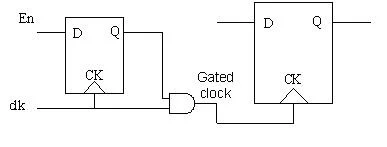
Clock being the highest frequency toggling signal contributes maximum towards the dynamic power consumption in the SoC even when the flops that are being fed by the clock are not changing their state. So, it is practical to gate the clock from reaching the set of registers or maybe some block in the design. This will ensure that there is no switching activity due to change in the clock and hence reduction in dynamic power consumption.


2. Power gating
Power gating is a technique to shut down the power of a block when it is not required to be On. i.e In Mobile voice processing block can be shut down when the user is not having an incoming or outgoing call. This is the best method of reducing power consumption.


3. Multiple Vt Library cells
Nowadays the user provides the same cells with two different threshold voltage in the library. So that synthesis tools can choose cells depending on the requirement. With low Vt, sub-threshold leakage will increase but speed will also be higher. So for timing critical path synthesis tool will insert low Vt cells and at another path high Vt cell.

4. Dynamic voltage and frequency scaling
Dynamic Voltage and Frequency Scaling (DVFS) describes the use of two power saving techniques (dynamic frequency scaling and dynamic voltage scaling). In this technique same block can be working at the different voltage at the different time .i.e some time it is required to do high computation (complex equation solver) task then it needs more speed so it can operate at high voltage. While some time low computation is required so it can operate at a lower voltage.

5. Supply voltage reduction
As power is directly proportional to voltage (p =iv), with a reduction in voltage, power consumption will reduce. But again with a reduction in voltage will reduce switching speed as well.

6. Multi-voltage design
In SOC some block ( RAM) are such which require higher speed, so that block can be powered with higher voltage. While some block (Peripheral device) which does not needs high speed so that block can be powered with lower voltage, which in turn can reduce leakage power. In earlier days people used to have the same voltage for the whole design which makes it necessary to operate at high voltage. While this new technique, we can achieve leakage reduction.

In upcoming posts, we will discuss more on UPF(Unified Power Format) and low power verification.

Sunday, 26 March 2017

Understanding real, realtime and shortreal variables of SystemVerilog

This post will help you to understand the difference between real, realtime and shortreal data types of SystemVerilog and its usage.

We faced some issue with real and realtime variable while writing a timing check.
Below is a simplified example of that check. 

`timescale 1ns/1fs;
module test; 
  real a,b;  
  realtime t1, t2;

initial 
begin 
  #1ns;
  t1 = $realtime;
  #1.8ns;
  t2 = $realtime;
  b = 1.8;
  a = t2 - t1; 

  if(a == b)
    $display("PASS a = %f b = %f", a,b);
  else
    $display("FAIL a = %f b = %f", a,b);

end 
endmodule 

and here is what we got the display

FAIL a = 1.800000 b = 1.800000  

How that happened !!! is really 1.800000 != 1.800000  !!!!

Now let's try something else, instead of using real we use shortreal

`timescale 1ns/1fs;
module test; 
  shortreal a,b;  
  realtime t1, t2;

initial 
begin 
  #1ns;
  t1 = $realtime;
  #1.8ns;
  t2 = $realtime;
  b = 1.8;
  a = t2 - t1; 

  if(a == b)
    $display("PASS a = %f b = %f", a,b);
  else
    $display("FAIL a = %f b = %f", a,b);

end 
endmodule 

Now the result was as expected !!

PASS a = 1.800000 b = 1.800000

To understand this lets go to SystemVerilog LRM. As per LRM 

The real data type is from Verilog-2001, and is the same as a C double
The shortreal data type is a SystemVerilog data type, and is the same as a C float.

So float is 32 bit data type and double is 64 bit data type. This sounds cool but still how 1.800000 != 1.800000

No ! it's not only about being 32 or 64 bit data type its more about precision."Precision is the main difference where float is a single precision (32 bit) floating point data type, double is a double precision (64 bit) floating point data type ".

To understand this difference let's go beyond and print the values with more number of digits after decimal point.

In below example we have used both real and shortreal to see the difference.

`timescale 1ns/1fs;
module test; 
  real a,b;
  shortreal c,d;
  realtime t1, t2, t3, t4;

initial 
  begin 
    #1ns;
    t1 = $realtime;
    #1.8ns;
    t2 = $realtime;
    b = 1.8;
    a = t2-t1;

    if(a == b)
      $display("Case1: PASS \na = %1.100f \nb = %1.100f", a,b);
    else
      $display("Case1: FAIL \na = %1.100f \nb = %1.100f", a,b);
  end 


initial 
  begin 
    #1ns;
    t3 = $realtime;
    #1.8ns;
    t4 = $realtime;
    d = 1.8;

    c = t2-t1;

    if(c == d)
      $display("Case2: PASS \nc = %1.100f \nd = %1.100f", c,d);
    else
      $display("Case2: FAIL \nc = %1.100f \nd = %1.100f", c,d);
  end 

endmodule

Here is what the display is

Case1: FAIL 
a = 1.7999999999999998223643160599749535322189331054687500000000000000000000000000000000000000000000000000 
b = 1.8000000000000000444089209850062616169452667236328125000000000000000000000000000000000000000000000000

Case2: PASS 
c = 1.7999999523162841796875000000000000000000000000000000000000000000000000000000000000000000000000000000 
d = 1.7999999523162841796875000000000000000000000000000000000000000000000000000000000000000000000000000000

It's clearly seen that the 64 bit real variable has more precision that that or 32 bit shortreal variable.  

Here one more thing to consider is that we are taking difference of time. Floating point math is not exact. Simple values like 0.1 cannot be precisely represented using binary floating point numbers, and the limited precision of floating point numbers means that slight changes in the order of operations or the precision of intermediates can change the result. That means that comparing two floats to see if they are equal is usually not what you want.

The things will not matter much if you are doing calculations in nanoseconds so we suggest to use shortreal instead of real.
  

Sunday, 15 January 2017

2017 VLSI Symposia on VLSI Techology and Circuits


For the past 30 years, the combined annual Symposia on VLSI Technology and Circuits have provided an opportunity for the world’s top device technologists, circuit and system designers to engage in an open exchange of leading edge ideas at the world’s premier mid-year conference for microelectronics technology. Held together since 1987, the Symposia on VLSI Technology and Circuits have alternated each year between sites in the US and Japan, enabling attendees to learn about new directions in the development of VLSI technology & circuit design through the industry’s leading research and development presentations.

The comprehensive technical programs at the two Symposia are augmented with short courses, invited speakers and several evening panel sessions. Since 2012, the Symposia have presented joint focus sessions that include invited and contributed papers on topics of mutual interest to both technology and circuit attendees. A single registration enables participants to attend both Symposia.

Online paper submission:

Online paper submissions are now open for the 2017 Symposia on VLSI Technology and Circuits, to be held at the Rihga Royal Hotel in Kyoto, Japan from June 5 – 8, 2017. In a departure from previous years, both Symposia (VLSI Technology and VLSI Circuits) will be held on a fully overlapping schedule from June 6 – 8, preceded by Short Courses on June 5.

The deadline for paper submissions to both Symposia is January 23, 2017. Complete details for paper submission can be found online at: http://vlsisymposium.org/authors.html

This year’s Symposia theme is “Harmonious Integration Toward Next Dimensions.” Authors are encouraged to submit papers that showcase innovations that extend beyond single ICs and into the module level, with co-optimization of device technology and circuit/system design, including focus areas in the Internet of Things (IoT), industrial electronics, ‘big data’ management, artificial intelligence (AI), biomedical applications, virtual reality (VR) / augmented reality (AR), robotics and smart cars. These topics will be featured in focus sessions as part of the program.

The Symposium on VLSI Technology seeks technical innovation and advances in all aspects of IC technology, as well as the emerging IoT (Internet of Things) field, including:

  • IoT systems & technologies, including ultra-low power, heterogeneous integration, wearable devices, sensors, connectivity, power management, digital/analog, microcontrollers and application processors
  • Stand-alone & embedded memories, including technology & reliability for DRAM, SRAM, (3D-)NAND, MRAM, PCRAM, ReRAM and emerging memory technologies
  • CMOS Technology, microprocessors & SoCs, including scaling, VLSI manufacturing concepts and yield optimization
  • RF / analog / digital technologies for mixed-signal SoC, RF front end; analog, mixed-signal I/O, high voltage, imaging, MEMS, integrated sensors
  • Process & material technologies, including advanced transistor process and architecture, modeling and reliability; alternate channel; advanced lithography, high-density patterning; SOI and III-V technologies, photonics, local interconnects and Cu/optical interconnect scaling
  • Packaging technologies & System-in-Package (SiP), including through-silicon vias (TSVs), power & thermal management, inter-chip communication, 3D-system integration, as well as yield & test issues
  • Photonics Technology & ‘Beyond CMOS’ devices

The Symposium on VLSI Circuits seeks original papers showcasing technical innovations and advances in the following areas:

  • Digital circuits, processors and architectures, including circuits and techniques for standalone and embedded processors
  • Memory circuits, architectures & interfaces for volatile and non-volatile memories, including emerging memory technologies
  • Frequency generation and clock circuits for high-speed digital and mixed-signal applications
  • Analog and mixed-signal circuits, including amplifiers, filters and data converters
  • Wireline receivers & transmitters, including circuits for inter-chip and long-reach applications
  • Wireless receivers & transmitters, including circuits for WAN, LAN, PAN, BAN, inter-chip and mm-wave applications
  • Power conversion circuits, including battery management, voltage regulation, and energy harvesting
  • Imagers, displays, sensors, VLSI circuits & systems for biomedical, healthcare and wearable applications

Joint Technology & Circuits focus sessions feature invited and contributed papers highlighting innovations and advances in the following areas of joint interest:

  • IoT /ULP (Internet of Things / Ultra Low Power) devices: Advanced CMOS processes for ULP, design enablement, design for manufacturing, process/design co-optimization, on-die monitoring of variability and reliability
  • New Computing: Artificial intelligence, ‘beyond von Neumann’ computing, machine learning, neuromorphic & in-memory / in-sensor computing
  • 2D MOSFETs / New concepts for channel & gate materials: Graphene, MoS2, α-Si / poly-Si or flexible organic materials for ‘More than Moore’ devices
  • Emerging memory technology & design: SRAM, DRAM, Flash, PCRAM, RRAM, and MRAM, Memristor, 3D Xpoint memory technologies
  • Design in scaled technologies: scaling of digital, memory, analog and mixed-signal circuits in advanced CMOS processes
  • 3D & heterogeneous integration: power and thermal management; inter-chip communications, SIP architectures and applications

Best Student Paper Award
Awards for best student paper at each Symposia are chosen based on the quality of the papers and presentations. The recipients will receive a monetary award, travel cost support and a certificate at the opening session of the 2018 Symposium. For a paper to be reviewed for this award, the author must be enrolled as a full-time student at the time of submission, must be the lead author and presenter of the paper, and must indicate on the web submission form that the paper is a student paper.

Sponsoring Organizations
The Symposium on VLSI Technology is sponsored by the IEEE Electron Devices Society and the Japan Society of Applied Physics, in cooperation with the IEEE Solid State Circuits Society.

The Symposium on VLSI Circuits is sponsored by the IEEE Solid State Circuits Society and the Japan Society of Applied Physics, in cooperation with the Institute of Electronics, Information and Communication Engineers and the IEEE Electron Devices Society.

Further Information, Registration and Official Call for Papers