Featured post

Top 5 books to refer for a VHDL beginner

VHDL (VHSIC-HDL, Very High-Speed Integrated Circuit Hardware Description Language) is a hardware description language used in electronic des...

Showing posts with label digital. Show all posts

Sunday, 27 May 2012

Dual Edge D-FlipFlop

One important design rule is to use only one edge of the clock signal. Although this is a good design practice in some special cases it might be helpful to use both edges.

Fig-1Fig. 1

Listing 1. not synthesizable dual-edge behavior in VHDL

process (reset, clock)
begin
if (reset =  ‘1’) then
−− reset
elsif rising_edge(clock) then
−− synchronous behavior
elsif falling_edge (clock) then
−− synchronous behavior
end if;
end process;

One example is low-power signal processing, where all state machines should run at the symbol frequency to avoid unnecessary switching. But the signal frequency might be higher than the symbol frequency.
FM0 encoding (fig. 1) is an example. With FM0 encoding always the signal switches at the begin of every symbol. Another signal switch is done in the middle of the symbol, if zero has to be transmitted. If a transmitter wants so send a FM0 encoded data stream and runs only at the symbol frequency, the output signal has to be switched with the rising edge of clock and additionally with the falling edge, if zero is transmitted.

Another example for dual-edge behavior are clock dividers. For odd divisors the divided clock signal has to be switched at the falling edge of the fast clock, to get the same length for the low and the high period.

There are two problems if dual-edge behavior is desired:

  1. Most cell libraries do not provide a dual-edge flip-flops.
  2. In VHDL dual-edge behavior can be described as shown in listing 1, but most synthesis tools do not support this. Only few are capable of handling such a description. Therefore we need another way to model dual-edge behavior.

Although dual-edge behavior is not supported by VHDL, synthesis and the cell libraries, a dual-edge flipflop can be described as shown in fig. 2. Note that synthesis tools will transform the multiplexers into XOR gates.

image Fig. 2. Pseudo Dual-Edge D-Flipflop (pde dff)

The pde dff consists of 2 cross-coupled flipflops, one triggered by the rising and the other one triggered by the falling edge of the clock signal c. The outputs of the flipflops are connected via an XOR gate. Although not shown in fig. 2, asynchronous set and reset are possible.

The synthesizable VHDL source code of the pde dff is shown in listing 2. Both asynchronous set (sn) and reset (rn) can be turned on or off using generic parameters. Using both edges of the clock means doubling the clock frequency. Propagation paths have to be half as long for dualedge logic compared to common single-edge logic.

Although the pde dff looks symmetric it has in general asymmetric behavior in terms of the propagation time for the rising and the falling edge of the data output q. It depends on the data input d, the stored values in the two flip-flops and the propagation times of both the flip-flops and the final XOR gate.

For the example of FM0 encoding (fig. 1) this means that for a continuous transmission of the symbol zero in general the time of the output q being high is not equal to the time of the output being low. Such an asymmetry is not uncommon even for single-edge flipflops but for the pde dff it is slightly bigger.

Listing2. The Pseudo Dual-Edge D-FF in VHDL:

library IEEE;
use IEEE.STD_LOGIC_1164.ALL;
IEEE.Numeric_std.ALL;

entity pdedff is
generic (
impl_rn: integer := 1; −− with async reset if 1
impl_sn: integer := 1); −− with async set if 1
port(
rn:in std_ulogic; −− low−active
sn:in std_ulogic; −− low−active
d:in std_ulogic;
c:in std_ulogic;
q:out std_ulogic);
end pdedff;

−−pseudo dual−edgeD−flipflop
−−reset and set are lowactive and can be
−−(de)activated using the generic paramters

architecture behavior of pdedff is
signal ff_rise, ff_fall:std_ulogic;
begin

process(rn, sn, c)
begin
if(impl_rn=1 AND rn=’0’) then
ff_rise <= ’0’;
elsif (impl_sn=1 AND sn=’0’) then
ff_rise <= ‘1’;
elsif rising_edge (c) then
if (d= ‘1’) then
ff_rise <= NOT (ff_fall);
else ff_rise <= ff_fall;
endif;
endif;
end process;

process(rn, sn, c)
begin
if(impl_rn = 1 AND rn= ‘0’) then
ff_fall <= ‘0’;
elsif (impl_sn= 1 AND sn = ‘0’) then
ff_fall <= ‘0’;
elsif falling_edge (c) then
if (d = ‘1’) then
ff_fall <= NOT (ff_rise);
else
fffall <= ff_rise;
endif;
endif;
end process;

q <= ‘0’ when (impl_rn = 1 AND rn= ‘0’) else
        ‘1’ when (impl_sn= 1 AND sn= ‘0’) else
        ff_rise XOR ff_fall;
−−rn and sn used to suppress spikes
endbehavior;

Monday, 28 November 2011

Cyclic Redundancy Checking (CRC)

Error detection is an important part of communication systems when there is a chance of data getting corrupted. Whether it’s a piece of stored code or a data transmission, you can add a piece of redundant information to validate the data and protect it against corruption. Cyclic redundancy checking is a robust error-checking algorithm, which is commonly used to detect errors either in data transmission or data storage. In this multipart article we explain a few basic principles.

Modulo two arithmetic is simple single-bit binary arithmetic with all carries or borrows ignored. Each digit is considered independently. This article talks about how modulo two addition is equivalent to modulo two subtraction, and can be performed using an exclusive OR operation followed by a brief on Polynomial division where remainder forms the CRC checksum.
For example, we can add two binary numbers X and Y as follows:

10101001 (X) + 00111010 (Y) = 10010011 (Z)

From this example the modulo two addition is equivalent to an exclusive OR operation. What is less obvious is that modulo two subtraction gives the same results as an addition.
From the previous example let’s add X and Z:

10101001 (X) + 10010011 (Z) = 00111010 (Y)

In our previous example we have seen how X + Y = Z therefore Y = Z – X, but the example above shows that Z+X = Y also, hence modulo two addition is equivalent to modulo two subtraction, and can be performed using an exclusive OR operation.

In integer division dividing A by B will result in a quotient Q, and a remainder R. Polynomial division is similar except that when A and B are polynomials, the remainder is a polynomial, whose degree is less than B.

The key point here is that any change to the polynomial A causes a change to the remainder R. This behavior forms the basis of the cyclic redundancy checking.
If we consider a polynomial, whose coefficients are zeros and ones (modulo two), this polynomial can be easily represented by its coefficients as binary powers of two.

In terms of cyclic redundancy calculations, the polynomial A would be the binary message string or data and polynomial B would be the generator polynomial. The remainder R would be the cyclic redundancy checksum. If the data changed or became corrupt, then a different remainder would be calculated.

Although the algorithm for cyclic redundancy calculations looks complicated, it only involves shifting and exclusive OR operations. Using modulo two arithmetic, division is just a shift operation and subtraction is an exclusive OR operation.

Cyclic redundancy calculations can therefore be efficiently implemented in hardware, using a shift register modified with XOR gates. The shift register should have the same number of bits as the degree of the generator polynomial and an XOR gate at each bit, where the generator polynomial coefficient is one.

Augmentation is a technique used to produce a null CRC result, while preserving both the original data and the CRC checksum. In communication systems using cyclic redundancy checking, it would be desirable to obtain a null CRC result for each transmission, as the simplified verification will help to speed up the data handling.

Traditionally, a null CRC result is generated by adding the cyclic redundancy checksum to the data, and calculating the CRC on the new data. While this simplifies the verification, it has the unfortunate side effect of changing the data. Any node receiving the data+CRC result will be able to verify that no corruption has occurred, but will be unable to extract the original data, because the checksum is not known. This can be overcome by transmitting the checksum along with the modified data, but any data-handling advantage gained in the verification process is offset by the additional steps needed to recover the original data.


Augmentation allows the data to be transmitted along with its checksum, and still obtain a null CRC result. As explained before when obtain a null CRC result, the data changes, when the checksum is added. Augmentation avoids this by shifting the data left or augmenting it with a number of zeros, equivalent to the degree of the generator polynomial. When the CRC result for the shifted data is added, both the original data and the checksum are preserved.

In this example, our generator polynomial (x3 + x2 + 1 or 1101) is of degree 3, so the data (0xD6B5) is shifted to the left by three places or augmented by three zeros.

0xD6B5 = 1101011010110101 becomes 0x6B5A8 = 1101011010110101000.

Note that the original data is still present within the augmented data.
0x6B5A8 = 1101011010110101000
Data = D6B5 Augmentation = 000

Calculating the CRC result for the augmented data (0x6B5A8) using our generator polynomial (1101), gives a remainder of 101 (degree 2). If we add this to the augmented data, we get:

0x6B5A8 + 0b101 = 1101011010110101000 + 101
= 1101011010110101101
= 0x6B5AD

As discussed before, calculating the cyclic redundancy checksum for 0x6B5AD will result in a null checksum, simplifying the verification. What is less apparent is that the original data is still preserved intact.

0x6B5AD = 1101011010110101101
Data = D6B5 CRC = 101

The degree of the remainder or cyclic redundancy checksum is always less than the degree of the generator polynomial. By augmenting the data with a number of zeros equivalent to the degree of the generator polynomial, we ensure that the addition of the checksum does not affect the augmented data.

In any communications system using cyclic redundancy checking, the same generator polynomial will be used by both transmitting and receiving nodes to generate checksums and verify data. As the receiving node knows the degree of the generator polynomial, it is a simple task for it to verify the transmission by calculating the checksum and testing for zero, and then extract the data by discarding the last three bits.

Thus augmentation preserves the data, while allowing a null cyclic redundancy checksum for faster verification and data handling.

Friday, 25 November 2011

Wednesday, 5 October 2011

Johnson Counter

The Johnson counter, also called the twisted ring counter, is a variation of the ring counter, with the inverse output of the most significant flip-flop passed to the input of the least significant flip-flop. The sequence followed begins with all 0's in the register. The final 0 will cause 1's to be shifted into the register from the left-hand side when clock pulses are applied. When the first 1 reaches the most significant flip-flop, 0's will be inserted into the first flip-flop because of the cross-coupling between the output and the input of the counter.

johnson_counter_truth_table

8_bit_johnson_counter

Links:

Ring counter

A ring counter is a circular shift register with only one flip-flop being set at any particular time; all others are cleared. The single bit is shifted from one flip-flop to the other to produce the sequence of timing signals.

ring_counter_statemachine

8_bit_ring_counter

Links:

BCD Counter

A BCD counter counts in binary-coded decimal from 0000 to 1001 and back to 0000. Because of the return to 0 after a count of 9, a BCD counter does not have a regular pattern as in a straight binary count.

bcd_counter

Links:

Loadable Counters

Instead of counting from 0, a counter can be made to count from a given initial value. This type of counter is called a loadable counter.

loadable_4bit_synchronous_counter

Links:

Tuesday, 27 September 2011

R-S Flip Flop

Fig 1The circuit of Fig.1 is called a SR flip-flop or bi-stable. We will consider its truth table, and immediately find that we have a problem. We can construct the table for the three states where at least one input is zero. This is because if any input to a nand gate is zero, the output will be one regardless of the other input, and we can therefore work around the loop to calculate all the values. However when R and S are 1 we cannot immediately calculate P and Q; so the only way we can analyze what happens is to look at the possible values that P and Q could hold. Thus we can expand the truth table to include a further two inputs Pp and Qp where the subscript p indicates the previous value.

S

R

Pp

Qp

P

Q


1

1

0

0

1

1

Unstable

1

1

0

1

0

1

Stable

1

1

1

0

1

0

Stable

1

1

1

1

0

0

Unstable

Here we see that there are two states where P=Pp and Q=Qp (1101 and 1110 respectively). These are therefore stable states. The other two states (1100 and 1111) are unstable, and using the simple model with time delay t will oscillate with a period of 2t. In practice, the circuit will fall into one of the two stable states rather than oscillate, since the time delays of the two nand gates will not be precisely the same. Which state if will finish in is non deterministic. In practice we are not interested in the non-deterministic states, only in the stable ones.

Fig.2This circuit can be considered to be a one bit memory circuit since Q can be set to one or zero. To see this we need to look at a sequence of inputs as shown in Fig.2. At the third time step we have the input 10 which puts the circuit into a known state and the output Q to 1. That value of Q is memorised and remains as long as the input is kept at 11. At the sixth time step the input 01 forces the output Q to be a 0, and as long as the input is held at 11 this 0 remains. This way of looking at the circuit gives rise to the names of the inputs S for Set and R for Reset, and so this flip flop is usually given the name R-S. The following three points should be noted. We are now describing the behaviour by means of a sequence of inputs, and for this reason, these circuits are referred to a sequential. Secondly, in all the cases of interest for this circuit P=Q'. Thirdly, an R-S flip flop can equivalently be built out of NOR gates.

Wednesday, 22 June 2011

4x1 Multiplexer Using 2x1 Multiplexer

Below Fig. shows the way to build 4x1 Multiplexer using three 2x1 Multiplexers.

4x1_mux_using_2x1_mux

Get free daily email updates!

Follow us!

Sunday, 8 May 2011

VLSI Interview Questions-1


1.What is the difference between mealy and moore state-machines.
2.How to solve setup and hold violations in the design.
3.What is antenna violation & ways to prevent it.
4.We have multiple instances in RTL(Register Transfer Language), do you do anything special during synthesis stage.
5.What is tie-high and tie-low cells and where it is used.
6.What is the difference between latches and flip-flops based designs.
7.What is High-Vt and Low Vt cells.
8.What is LEF mean?
9.What is DEF mean?
10.Steps involved in designing an optimal padring.
11.What is metastability and steps to prevent it.
12.What is local-skew, global skew and useful skew.
13.What are the various timing-paths which i should take care in my STA runs?
14.What are the various components of leakage-power.
15.What are the various yield losses in the design.
16.What is meant by virtual clock definition and why do i need it.
17.What are the various variations which impacts timing of the design.
18.What are the various Design constraints used, while performing synthesis for a design.
19.Specify few verilog constructs which are not supported by the synthesis tool.
20.What are the various capacitances with an MOSFET?
21.Vds-Ids curve for an MOSFET, with increasing Vgs.
22.Explain basic operation of an MOSFET.
23.what is channel length modulation.
24.what is body effect.
25.what is latchup in CMOS design and ways to prevent it?
26.what are the various design changes you do to meet design power targets.
27.what is meant by library characterization.
28.what is meant by wireload model.
29.what are the measures to be taken to design for optimized area.
30.what all will you be thinking while performing floorplan.
31.what are the measures in the design taken for meeting signal integrity targets.
32.what are the measures taken in the Design achieving better yield.
33.what are the measures or precautions to be taken in the design when the chip has both analog and digital portions..
34.what are the steps incorporated for Engineering Change order[ECO].
35.what are the steps performed to achieve Lithography friendly Design.
36.what does synthesis mean?
37.what are the pre-requistes to perform synthesis.
38.Can you explain the synthesis flow.
39.what are the various ways to reduce clock insertion delay in the design.
40.what are the various functional verification methodologies.
41.what does formal verification mean.
42.How will you time the output path in STA.
43.How will you time the input path in STA.
44.What is false path mean in STA and in what scenarios falsepath can come.
45.What does multicycle path mean in STA and in what scenarios MCP can come.
46.What are source synchronous paths in STA.
47.Assume there is a specific requirement to preserve the logic during synthesis , how will you achieve it..
48.we have multiple instances in RTL, do you do anything special during synthesis stage.
49.What do you call an event and when do you call an assertion.

Friday, 30 April 2010

Positive and Negative Edge Detector Circuit

Positive and negative edge detection is a common requirement in microprocessors. One application could be to detect edge/level triggered events on certain GPIO inputs. Here i will show you a simple circuit which is use to detect Positive as well negative edges.


VHDL CODE : 

library ieee;
use ieee.std_logic_1164.all;
entity edge is
   port (
    inp        : in  std_logic;         -- inpit
    clk        : in  std_logic;         -- clock
    rst        : in  std_logic;         -- reset
    edge_op : out std_logic);        -- setected edge output
 end edge;

architecture edge_ar of edge is
  signal sig1 : std_logic;              -- signal from 1st flop
  signal sig2 : std_logic;              -- signal from 2nd flop


begin  -- edge_ar
   edge : process(clk, rst)
  begin
    if rst = '1' then
      sig1 <= '0';
      sig2 <= '0';
    elsif clk'event and clk = '1' then
      sig1 <= inp;
      sig2 <= sig1;
    end if;
  end process edge;

  edge_op <= sig1 xor sig2;

end edge_ar;


Saturday, 3 April 2010

What is Clock Skew?

Given two sequentially-adjacent registers, Ri and Rj, and an equipotential clock distribution network, the clock skew between these two registers is defined as


Tskew-i,j = Tci - Tcj


where Tci and Tcj are the clock delays from the clock source to the registers Ri and Rj, respectively.


Friday, 26 February 2010

De-Multiplexer

The de-multiplexer is the inverse of the multiplexer, in that it takes a single data input and n address inputs. It has 2n outputs. The address input determine which data output is going to have the same value as the data input. The other data outputs will have the value 0.


Encoder

Just opposite to decoder an encoder has many inputs but less outputs.
Below figure shows an example of 4-to-2 Encoder 


Multiplexer

A multiplexer performs the function of selecting the input on any one of 'n' input lines and feeding this input to one output line.


Assume that we have four lines, C0C1C2 and C3, which are to be multiplexed on a single line, Output (f). The four input lines are also known as the Data Inputs. Since there are four inputs, we will need two additional inputs to the multiplexer, known as the Select Inputs, to select which of the C inputs is to appear at the output. Call these select lines A and B.
The gate implementation of a 4-line to 1-line multiplexer is shown below:


Tuesday, 2 February 2010

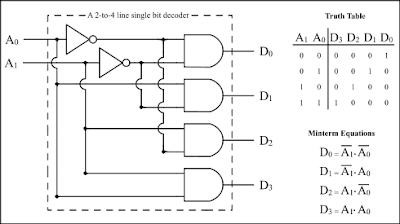
Decoder

Decoder is a multiple input; multiple output logic circuit that converts coded inputs in coded outputs, where input and output codes are different.

Inputs have fewer inputs than output. Below is a simple example of 2-to-4 decoder.


Sunday, 18 October 2009

Sequential Circuits


Sequential logic differs from combinational logic in that the output of the logic device is dependent not only on the present inputs to the device, but also on past inputs; i.e., the output of a sequential logic device depends on its present internal state and the present inputs. This implies that a sequential logic device has some kind of memory of at least part of its ``history'' (i.e., its previous inputs). Below figure shows a generic structure for sequential circuit.


The memory elements are devices capable of storing binary info. The binary info stored in the memory elements at any given time defines the state of the sequential circuit. The input and the present state of the memory element determines the output. Memory elements next state is also a function of external inputs and present state. A sequential circuit is specified by a time sequence of inputs, outputs, and internal states.

There are two types of sequential circuits. Their classification depends on the timing of their signals:

  • Synchronous sequential circuits
  • Asynchronous sequential circuits


  • Asynchronous sequential circuits: This is a system whose outputs depend upon the order in which its input variables change and can be affected at any instant of time.

    Gate-type asynchronous systems are basically combinational circuits with feedback paths. Because of the feedback among logic gates, the system may, at times, become unstable. Consequently they are not often used. Below is an example circuit.


    Synchronous sequential circuits:This type of system uses storage elements called flip-flops that are employed to change their binary value only at discrete instants of time. Synchronous sequential circuits use logic gates and flip-flop storage devices. Sequential circuits have a clock signal as one of their inputs. All state transitions in such circuits occur only when the clock value is either 0 or 1 or happen at the rising or falling edges of the clock depending on the type of memory elements used in the circuit. Synchronization is achieved by a timing device called a clock pulse generator. Clock pulses are distributed throughout the system in such a way that the flip-flops are affected only with the arrival of the synchronization pulse. Synchronous sequential circuits that use clock pulses in the inputs are called clocked-sequential circuits. They are stable and their timing can easily be broken down into independent discrete steps, each of which is considered separately.
    Below figure shows example circuit:


    A clock signal is a periodic square wave that indefinitely switches from 0 to 1 and from 1 to 0 at fixed intervals. Clock cycle time or clock period: the time interval between two consecutive rising or falling edges of the clock.

    Thursday, 15 October 2009

    Combinational circuits


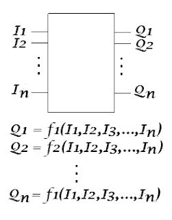
    Combinatorial Circuits are circuits which can be considered to have the following generic structure.

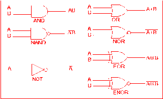
    Whenever the same set of inputs is fed in to a combinatorial circuit, the same outputs will be generated. Such circuits are said to be stateless. Some simple combinational logic elements that we have seen in previous sections are "Gates".

    Below figure shows the basic gates that are used to build a combinational circuit.

    Tuesday, 13 October 2009

    Digital Design

    As i have mentioned earlier that digital design concepts has to be crystal clear while you design a digital circuit. Here we will stat with the basic concepts of digital designing.

    Digital or binary logic has fascinated many people over the years. The very idea that a two-valued number system can possibly be the basis for the most powerful and sophisticated computers seems astounding, to say the least. Nevertheless, it is so, and the how and the why of this requires some explanation.

    Everything in the digital world is based on the binary number system. Numerically, this involves only two symbols: 0 and 1. Logically, we can use these symbols or we can equate them with others according to the needs of the moment. Thus, when dealing with digital logic, we can specify that:

    0 = false = no
    1 = true = yes

    Using this two-valued logic system, every statement or condition must be either "true" or "false;" it cannot be partly true and partly false. While this approach may seem limited, it actually works quite nicely, and can be expanded to express very complex relationships and interactions among any number of individual conditions.

    Digital logic may be divided into two classes:

    => combinational logic, in which the logical outputs are determined by the logical function being performed and the logical input states at that particular moment. A simple combinational circuit is shown below.


    =>sequential logic, in which the outputs also depend on the prior states of those outputs. Both classes of logic are used extensively in all digital computers. A Latch is considered to be a simplest sequential circuit. A simple sequential circuit is shown below.