Featured post

Top 5 books to refer for a VHDL beginner

VHDL (VHSIC-HDL, Very High-Speed Integrated Circuit Hardware Description Language) is a hardware description language used in electronic des...

Monday, 21 November 2016

Advantages of Python over Perl

In the new competitive generation of chip designing where Time-to-Market is so critical and also the complexity of designs is increasing exponentially.  Adding to that it is also observed that the Verification is always considered the longest pole and takes nearly 70% of the chip design life cycle. Hence any opportunity to automate a  task that is repeatable more than once is considered of most importance to improve the verification productivity. This is where  “scripting” skills are highly valuable for any  Verification engineer.

After many years of writing design and verification automation scripts in Perl and Python, we would like to throw some light on the advantages of using Python.

Maintainability

As we all know, Perl is easy to write but hard to read, especially when someone else has written it. There are multiple ways of writing the same code. Add to this fact that many engineers take pride in writing highly obfuscated Perl that is a pain for others to read.

Maintainability is a critical aspect of any engineering project. Throwing away code and rewriting it is a productivity loss. Unfortunately, this happens a lot with Perl.

Python, on the other hand, has a clean syntax and typically there is only one way of doing what you want. Python code is hence much more readable. Even people who have never written Python code ever can understand it, as the syntax is very “pseudo-code” like. It is also easier to functionalize and modularize code in Python as the language naturally encourages this.

Re-usability

Perl is designed for use and throw. You write something in Perl, run it and then forget about it. It is very difficult to extend the functionality of a Perl script. Typically you would not have organized your code into functions, as Perl syntax does not encourage that. When you try adding some functionality to your Perl script you realize that re-writing it completely is better than re-using the earlier script and extending it.

Python syntax encourages re-usability. The mindset is different. When you write code in Python, you write with future re-usability in mind. This is really tough to do in Perl. Perl encourages shortcuts.

Scale

Writing large pieces of code (more than 50k lines) in Perl exposes the weaknesses in the language. Maintainability, performance, and packaging are big issues. Can I package my application in a way that doesn’t require users to download and install modules used by the application?

Perl encourages users to download and install modules as needed. IT departments are not comfortable with upgrading Perl installations on thousands of server farm nodes. It would be an IT nightmare.

Python distributions, on the other hand, come with a majority of the module libraries included. Also, Python allows the packaging of applications so users do not have to manually download and install all module and library dependencies needed to run an application.

Final words

Perl is great at some things. For example, it has fantastic regular expression capabilities (it can even combine multiple regexp’s and match all of them together!). Perl is a worthy successor to awk.

Bottom line:  For use and throw scripts, Perl is great. But, if your code needs to be checked into a version control system and will potentially be modified by other people, I would prefer Python over Perl.

Saturday, 19 November 2016

Transaction Recording In Verilog Or System Verilog

As there is not yet a standard for transaction recording in Verilog or VHDL, ModelSim includes a set of system tasks to perform transaction recording into a WLF file. Transaction modeling allows users to raise the level of description, analysis and debugging of their designs to the transaction level. A transaction represents a transfer of high-level data or control information between the test bench and the design under test (DUT) over an interface or any sequence of signal transitions recorded in the simulation database as a transaction.


The API is the same for Verilog and SystemVerilog. As stated previously, the name "Verilog" refers both to Verilog and SystemVerilog unless otherwise noted.
The recording APIs for Verilog and VHDL are a bit simpler than the SCV API. Specifically, in Verilog and VHDL:
  • There is no database object as there is in SCV; the database is always WLF format (a .wlf file).
  • There is no concept of begin and end attributes All attributes are recorded with the system task $add_attribute() or add_attribute.

  • Your design code must free the transaction handle once the transaction is complete and all use of the handle for relations or attribute recording is complete. (In most cases, SystemC designs ignore this step since SCV frees the handle automatically.)
A transaction has a begin time, an end time, and attributes. Examples of transactions include read operations, write operations, and packet transmissions. The transaction level is the level at which many users think about the design, so it is the level at which you can verify the design most effectively.

Transactions are recorded on a stream. A stream is a collection of transactions, recorded over time. A stream has a name, and usually exists somewhere within the test bench hierarchy – for example a driver might have a stream which represents all the transactions that have occurred on that driver. Each driver defines a collection of attributes ( transaction items ) which are defined by users, and which are meaningful to the transaction. The values of attributes are set for each transaction. Finally, transactions can be linked to each other. A link has a direction and a user-defined name, and specifies a relation between the two transactions.


module top;
    integer stream, tr;
    initial begin
        stream = $create_transaction_stream("Stream");
        #10;
        tr = $begin_transaction(stream, "Tran1");
        $add_attribute(tr, 10, "beg");
        $add_attribute(tr, 12, "special");
        $add_attribute(tr, 14, "end");
        #4;
        $end_transaction(tr);
        $free_transaction(tr);
    end

endmodule

Here,

1. $create_transaction_stream() is used to define a transaction stream. You can use this system task to create one or more stream objects.

 module top;
        integer hStream

        initial begin
            hStream = $create_transaction_stream("stream", "transaction");
            .
            .
        end
        .
        .
    endmodule

2. $begin_transaction is used to start a transaction by providing a valid handle of the transaction as shown below.


integer hTrans;
.
.
 hTrans = $begin_transaction(hstream, "READ");


In this example, we begin a transaction named "READ" on the stream already created. The $begin_transaction system function accepts other parameters to specify: the start time for the transaction, and any relationship information, including its designation as a phase transaction.
The return value is the handle for the transaction. It is needed to end the transaction or record attribute.

3. $end_transaction has a single required argument – the handle of the transaction that is to be ended. It also has a single optional argument, the time in the past that this transaction ended. After a transaction has been ended, the transaction handle can still be used to add attributes and create relations.

$end_transaction( handle transaction [, time endTime])

4. $free_transaction has a single argument – the handle of the transaction to be deleted. Once a transaction is deleted the handle becomes invalid. It cannot be used in any other recording interfaces.

$free_transaction (handle transaction)

5. $add_attribute has two required arguments – a transaction handle on which the attribute is to be created and the attribute that is to be recorded. There is one optional argument of type string named attributeName. This attributeName specifies an alias name for the attribute. If not specified, the name used for the attribute is the actual name of the SystemVerilog object.

$add_attribute( handle transaction,  object attributeValue  [, string attributeName])

6. $add_relation has three arguments – the first two are the two transaction handles which are related. The third argument is the string name of the relation.

$add_relation( handle sourceTransaction,  handle targetTransaction,  string relationshipName)

Saturday, 22 October 2016

Build smart tests using uvm_report_catcher

Today we will look into a very useful concept of UVM specially when we are doing any erroneous testing. Its all about modifying the severity, id, action, verbosity or the report string itself before the report is finally issued by the report server. 

Normally in our test environment shout for error when any erroneous scenario like CRC error condition or generation of any error interrupt occurs. And we also write erroneous tests to test these scenarios where we end-up with error messages and tests fails. 

The uvm_report_catcher is used to catch messages issued by the uvm report server. Upon catching a report, the catch method can modify the severity, id, action, verbosity or the report string itself before the report is finally issued by the report server.  The report can be immediately issued from within the catcher class by calling the issue method.

The catcher maintains a count of all reports with FATAL, ERROR or WARNING severity and a count of all reports with FATAL, ERROR or WARNING severity whose severity was lowered.  These statistics are reported in the summary of the uvm_report_server.

Example: 

Report catcher class:
class error_report_catcher extends uvm_report_catcher;
  //new constructor
  virtual function action_e catch();
    if(get_severity() == UVM_ERROR && get_id() == "MON_CHK_NOT_VALID") begin
      set_severity(UVM_INFO);
      return CAUGHT;
    end
    else begin
      return THROW;
    end
  endfunction
endclass : error_report_catcher_c


Use of error catcher in testcase: 
class erroneous_test extends base_test_class;

  // report catcher to suppress errors
  error_report_catcher error_catcher ;
  /// \fn new_constructor
   
  /// \fn build_phase
virtual function void build_phase(uvm_phase phase);
    super.build_phase(phase);
      error_catcher = new();
      uvm_report_cb::add(null,error_catcher) ;
      uvm_config_db#(int)::set(this,“uvc.tx_agent","is_active",UVM_ACTIVE);
         
      // User configurations
      env_cfg.print();
      uvm_config_db#(env_config_c)::set(this, "*" , “env_cfg", env_cfg);
      // Calling the error sequence
      uvm_config_db#(uvm_object_wrapper)::set(this, “uvc.tx_agent.tx_sequencer.main_phase","default_sequence",valid_invalid_seq_c::type_id::get());
  endfunction : build_phase

endclass : erroneous_test

Sunday, 11 September 2016

64 core processor from Chinese chip maker Phytium

While the world awaits the AMD K12 and Qualcomm Hydra ARM server chips to join the ranks of the Applied Micro X-Gene and Cavium ThunderX processors already in the market, it could be upstart Chinese chip maker Phytium Technology that gets a brawny chip into the field first and also gets traction among actual datacenter server customers, not just tire kickers.

Phytium Technology has announced a 64-core ARM server CPU, which according to the press release will deliver 512 gigaflops of performance. The new chip, known as FT-2000/64, is aimed at “high throughput and high performance servers.”

Phytium is a chip design enterprise, based in Tianjin, China. In March 2015, the company released its first products: the FT-1500A/4 and FT-1500A/16, 4-core and 16-core implementations, respectively of the ARMv8 design.

Phytium was on hand at last week’s Hot Chips 28 conference, showing off its chippery and laptop, desktop and server machines employing its “Earth” and “Mars” FT series of ARM chips. Most of the interest that people showed in the server variants, which are both based on variants of the “Xiaomi” core design that the company has cooked up based on ARMv8 intellectual property licensed from ARM Holdings. There is chatter that one of the three Chinese exascale machines, which we wrote about here, will employ a future Phytium processor, but we were unable to confirm this with the Phytium executives at the event. What we can tell you is that the first engineering samples of the two Earth ARM chips, the FT-1500A/4 and the FT-1500A/16, as well as the one Mars ARM chip, the FT-2000/64, are back from Taiwan Semiconductor Manufacturing Corp and that we saw systems running the Kylin Linux operating system (a variant of Canonical’s Ubuntu) at the Hot Chips event.

Here are the key chip features from the FT-2000/64 product page: 

  • Process:Manufacturing with 28nm process
  • Core:Integrating sixty-four FTC661 cores
  • Frequency:Running at 1.5GHz~2.0GHz
  • Cache:Integrating 32MB L2 cache and extending 128MB LLC
  • Extension Interface:Integrating eight proprietary extension interfaces, each delivering 19.2GB/s effective r/w bandwidth
  • Memory Interface:Extending sixteen DDR3-1600 memory controllers, which can deliver 204.8GB/s memory access bandwidth.
  • I/O Interface:Integrating two x16 or four x8 PCIE Gen3 interface
  • Power:Max. power 100W
  • Package:FCBGA package with 2892 pins
No pricing was provided on the new chips, and it’s unclear from the press release if the product is available today. The next time we hear about the FT-2000/64 might very well be when it shows up in a TOP500 supercomputer. Stay tuned.

4μm thick fabric like flexible circuit

According to the Korea Advanced Institute of Science and Technology (KAIST), complete with substrate, an active matrix for a flexible display need only be 4μm thick. 

Initially on a sacrificial laser-reactive substrate the matrix of ultra-thin n-type transparent oxide thin-film transistors (TFTs) were fabricated for the back plane.

Laser irradiation from the backside of the substrate split off only the oxide TFT array as a result of reaction with the laser-reactive layer.

The free transistors were transferred to a 4μm  polyethylene terephthalate (PET) substrate, and then the combination was further transferred con-formally to the surface of human skin and artificial leather to demonstrate the possibility of the wearable application.

“The attached oxide TFTs showed high optical transparency of 83% and 40cm2/Vs even under several cycles of severe bending tests,” said KAIST.

The method is called inorganic-based laser lift-off (ILLO).

“By using our ILLO process, the technological barriers for high performance transparent flexible displays have been overcome at a relatively low cost by removing expensive polyimide substrates. Moreover, the high-quality oxide semiconductor can be easily transferred onto skin-like, or any flexible, substrate for wearable application,” said Professor Keon Jae Lee.

Con-formal displays are a potential application.

“With the advent of the Internet of Things era, demand has grown for wearable and transparent displays that can be applied to fields such as augmented reality and skin-like thin flexible devices,” said KAIST. “However, previous flexible transparent displays have poor transparency and low electrical performance. To improve the transparency and performance, past research efforts have tried to use inorganic-based electronics, but the fundamental thermal instabilities of plastic substrates have hampered the high temperature process, an essential step necessary for the fabrication of high performance electronic devices.”

Monday, 18 July 2016

Mega Processor to Understand Micro Processor

MegaProcessor Panaroma Image

Have you ever imagine how the work or what's going on inside? Think about a bigger version of a microprocessor where you can walk inside and look how it is working in real.

You may have heard that your smartphone contains more computing power than all the computers used on the Apollo mission combined. But imagine taking the computing power of a Super Nintendo, and packing it into a computer the size of--a living room?

The "mega-processor" is essentially a blown up version of a tiny chip that allows you to see how all the elements of a computer chip join together and how it actually works.

A Cambridge resident has finished building a 10-metre wide and 2-metre high computer in his living room, which he uses to play the video game Tetris.

James Newman took four years and £40,000 to build the processor which works exactly like a small microprocessor chip in a regular desktop computer or laptop that's about the size of a sim card.

This room-sized megaprocessor has 40,000 transistors, 10,000 LED lights, weighs around half a tonne (500kg) and burns 500W of electricity, according to Newman, who explains the entire contraption in a video.


James Newman said his Mega Processor relies almost entirely on the hand-soldered components, and will ultimately demonstrate how data travels through and is processed in a simple CPU core. He's just finished putting together the general purpose registers, and in May completed the arithmetic and logic unit.

Each transistor acts like a digital switch, and can be chained together to form huge decision-making circuits that execute software, instruction by instruction.

Newman, whose background is in software development and FPGA programming, told The Register he has spent about £40k on the project to date. He started planning the processor in 2012, and began building the beast a year later.

Monday, 4 July 2016

The World's First 1,000 Processor Chip ( KiloCore Chip )

A team of scientists from the University of California has created the world's first microchip with 1,000 independent processors. Called 'KiloCore' chip, it is also claimed to be the world's fastest chip ever designed at a university. The chip, which was presented this week at the 2016 Symposium on VLSI Technology and Circuits, is capable of 1.78 trillion instructions per second and contains 621 million transistors. The partially Department of Defense-funded KiloCore chip was ultimately built by IBM using existing 32 nanometer semiconductor fabrication technology.

Unfortunately, a 1,000 core chip isn't something that could just be plugged into the next line of MacBook Pros. It wouldn't even really suffice as a graphics processor, where massively parallel computation is the norm. In fact, many GPUs exceed the 1,000 cores of the UC Davis chip, but with the caveat that the individual cores are directed according to a central controller. The KiloCore, by contrast, is built from completely independent cores capable of running completely independent computer programs.

Here's all you need to know about the chip:
  • This microchip has been designed by a team at the University of California, Davis, Department of Electrical and Computer Engineering.
  • KiloCore chip executes instructions more than 100 times more efficiently than a modern laptop processor.
  • Each processor core can run its own small program independently of the others, which is a fundamentally more flexible approach than the Single-Instruction-Multiple-Data approaches utilized by processors such as graphics processing unit (GPU). Because each processor is independently clocked, it can shut itself down to further save energy when not needed.
  • The chip has been fabricated by IBM using its 32nm CMOS technology. KiloCore's each processor core can run its own small program independently of the others.
  • Cores operate at an average maximum clock frequency of 1.78 GHz, and they transfer data directly to each other rather than using a pooled memory area that can become a bottleneck for data.

The independence of the cores makes the KiloCore chip a multiple instruction multiple data (MIMD) computer. This is in contrast to the more typical single instruction multiple data (SIMD) variety of parallel computation, as would be expected in a graphics processor. A SIMD machine's version of parallelism is to implement the same single operation across many different cores - that is, do the same thing to many different units of data. This is the norm in image processing, for example, where a lot of different pixels holding different a lot of different values are all updated in the same way. A MIMD machine can be expected to do much more complex calculations.

Together, the 1,000 processors can execute 115 billion instructions per second while dissipating only 0.7 Watts. As noted in a UC Davis press release, this power requirement is low enough that it could be supplied by a single AA battery, achieving an efficiency of around 100 times that of a normal laptop processor.


The energy savings here largely has to do with the abandoning of the traditional system memory architecture, in which data for multiple cores is stored in a central RAM unit. Rather than sharing data in this way, the KiloCore chip uses a built-in networking scheme in which data is transferred directly between the different processors using packet- and circuit-switched networking.

Friday, 22 January 2016

Radix number systems and conversions

We have learned and use the decimal numbering system simply because humans are born with ten fingers! Hence, the numeric system we is the decimal number system, but this system is not convenient for machines since the information is handled codified in the shape of ON or OFF bits.

This means, we have to learn the binary system in addition to the decimal system. We also will discuss the octal and hexadecimal systems because conversion to/from binary is easy and numbers in these systems are easier to read than binary numbers for humans. 

This way of codifying takes us to the necessity of knowing the positional methods of calculation which will allow us to express a number in any base where we need it.

A base of a number system or radix defines the range of values that a digit may have.

Binary Number System
In the binary system or base 2, there can be only two values for each digit of a number, either a "0" or a "1".
Digital and computer technology is based on the binary number system, since the foundation is based on a transistor, which only has two states: on or off.

Each digit of the number is called a bit or which is a short for binary digits.
  • An 8-bit group is referred to as a Byte
  • An 4-bit group is referred to as a nibble

Each bit is weighted based on its position in the sequence (powers of 2) from the Least
Significant Bit (LSB) to the Most Significant Bit (MSB).

Each bit must be less than 2 which means it has to be either 0 or 1.

For example (1010.11)2 is evaluated as:


(1010.11)2 = 8 + 0 + 2 + 0 + 0.5 + 0.25 = (10.75)10 

Note: The general term for decimal point is radix point

In binary, the count starts at 0 (called 0-referencing), where in decimal, the count typically starts
with 1 (called 1-referencing


Octal Number System
In the octal system or base 8, there can be eight choices for each digit of a number:
"0", "1", "2", "3", "4", "5", "6", "7".

Octal number systems are used by humans as a representation of long strings of bits since they are:

  • Easier to read and write, for example 347 in octal is easier to read and write than 011100111 in binary.
  • Easy to convert (Groups of 3 or 4)
  • The most common way is to use Hex to write the binary equivalent; two hexadecimal digits make a Byte (groups of 8-bit), which are basic blocks of data in Computers.

Decimal Number System
In the decimal system or base 10, there are ten different values for each digit of a number:
"0", "1", "2", "3", "4", "5", "6", "7", "8", "9".

Decimal number system is default and easy to use for us. For example when you see a number 56 your assumption is that its base or radix is 10 i.e. “56 base 10”.

  • Each digit is weighted based on its position in the sequence (power of 10) from the Least Significant Digit (LSD, power of 0) to the Most Significant Digit (MSD, highest power).  
  • Each digit must be less than 10 (0 to 9) 
Hexadecimal Number System
In the hexadecimal system, we allow 16 values for each digit of a number:
"0", "1", "2", "3", "4", "5", "6", "7", "8", "9", "A", "B", "C", "D", "E", and "F".

Where “A” stands for 10, “B” for 11 and so on.

Conversion among different radices

1. Convert from Decimal to Any Base
Let’s think about what you do to obtain each digit. As an example, let's start with a decimal number 1234 and convert it to decimal notation. To extract the last digit, you move the decimal point left by one digit, which means that you divide the given number by its base 10.

 1234/10 = 123 + 4/10

The remainder of 4 is the last digit. To extract the next last digit, you again move the decimal point left by one digit and see what drops out.

 123/10 = 12 + 3/10

The remainder of 3 is the next last digit. You repeat this process until there is nothing left. Then you stop. In summary, you do the following: 


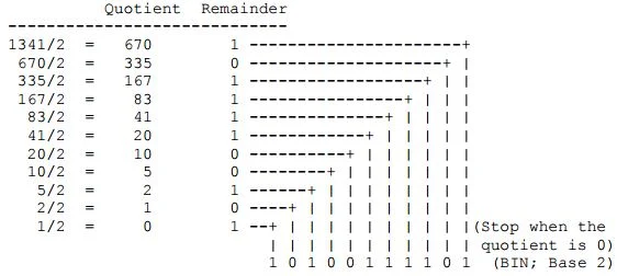
Conversion of decimal number to binary
Now, let's try a nontrivial example. Let's express a decimal number 1341 in binary notation. 
Note that the desired base is 2, so we repeatedly divide the given decimal number by 2


Conversion of decimal number to octal
Now, let's express the same decimal number 1341 in octal notation. 


Conversion of decimal number to hexadecimal
Let's express the same decimal number 1341 in hexadecimal notation. 

The easiest way to convert fixed point numbers to any base is to convert each part separately. We begin by separating the number into its integer and fractional part. The integer part is converted using the remainder method, by using a successive division of the number by the base until a zero is obtained. At each division, the reminder is kept and then the new number in the base r is obtained by reading the remainder from the lat remainder upwards.

The conversion of the fractional part can be obtained by successively multiplying the fraction with the base. If we iterate this process on the remaining fraction, then we will obtain successive significant digit. This methods form the basis of the multiplication methods of converting fractions between bases.

Example:
Convert the decimal number 3315 to hexadecimal notation. What about the hexadecimal equivalent of the decimal number 3315.3? 

Solution:

Conversion of Any Base to Decimal
Let's try to understand what a decimal number means. For example, 1234 means that there are four boxes (digits); and there are 4 one's in the right-most box (least significant digit), 3 ten's in the next box, 2 hundred's in the next box, and finally 1 thousand's in the left-most box (most significant digit). The total is 1234:


or simply, 1*1000 + 2*100 + 3*10 + 4*1 = 1234

Thus, each digit has a value: 10^0 =1 for the least significant digit, increasing to 10^1 =10, 10^2 =100, 10^3 =1000, and so forth.

Likewise, the least significant digit in a hexadecimal number has a value of

16^0 =1 for the least significant digit, increasing to
16^1 =16 for the next digit,
16^2 =256 for the next,
16^3 =4096 for the next, and so forth.

Thus, 1234 means that there are four boxes (digits); and there are 4 one's in the right-most box (least significant digit), 3 sixteen's in the next box, 2 256's in the next, and 1 4096's in the left-most box (most significant digit). The total is:

1*4096 + 2*256 + 3*16 + 4*1 = 4660

In summary, the conversion from any base to base 10 can be obtained from the formulae


Where b is the base, di the digit at position i, m the number of digit after the decimal point, n the number of digits of the integer part and X10 is the obtained number in decimal. This form the basic of the polynomial method of converting numbers from any base to decimal

Example: Convert 234.14 expressed in an octal notation to decimal.


Example: Convert the hexadecimal number 4B3 to decimal notation. What about the decimal equivalent of the hexadecimal number 4B3.3?


Example:  Convert 234.14 expressed in an octal notation to decimal.